Vehicle-mounted antenna device

a technology of antenna devices and antennas, which is applied in the direction of resonant antennas, printed circuit non-printed electric components association, electrical apparatus casings/cabinets/drawers, etc., can solve the problems of increased temperature, increased transmission loss, and loss of transmission cables, so as to reduce the degradation of circuit section performance caused by temperature increase, the effect of radiating sun radiation and transfer to the circuit section

Active Publication Date: 2017-02-28
DENSO CORP
View PDF12 Cites 0 Cited by
  • Summary
  • Abstract
  • Description
  • Claims
  • Application Information

AI Technical Summary

Benefits of technology

[0005]In antenna devices, as frequencies of radio waves to be used become higher, loss in a transmission cable, i.e., transmission loss becomes more significant. In particular, an antenna device used for vehicle-to-vehicle communication and vehicle-to-road-side communication uses radio waves of a high frequency of 5.9 GHz band to be used become higher, and therefore the transmission loss becomes significant. The transmission loss may be reduced by forming an antenna element section on a board to be stood on a base and by implementing a circuit section serving as at least part of a wireless communication circuit on the board so that the circuit section can be located close to the antenna element section.
[0008]In view of the above, it is an object of the present disclosure to reduce degradation in performance of a circuit section without loss of design of a housing in a vehicle-mounted antenna device which uses radio waves of a high frequency.
[0010]Thus, since the circuit section is implemented on the board, i.e., since the circuit section is located close to the antenna element section, transmission loss can be reduced even when radio waves of a high frequency are used. Therefore, for example, the vehicle-mounted antenna device can be suitable for applications where radio waves of a frequency of a few GHz band are used.
[0011]Further, the heat transfer path having a thermal conductivity higher than that of air is formed between the circuit section and the housing without passing the base. Thus, although the circuit section is located in the space between the housing and the base, heat generated in the circuit section can be dissipated to the housing. Further, heat radiated from the sun and transferred from the roof to the circuit section through the board can be dissipated to the housing. Therefore, degradation in performance of the circuit section caused by a temperature increase can be reduced without loss of design of the housing. It is noted that the meaning of “stood” is that the board is mounted on the base so that a thickness direction of the board can be different from a direction perpendicular to the base.
[0013]Since the circuit section is located away from the base, the heat radiated from the sun and transferred to the circuit section can be reduced. Accordingly, the degradation in the performance of the circuit section caused by the temperature increase can be reduced.

Problems solved by technology

In antenna devices, as frequencies of radio waves to be used become higher, loss in a transmission cable, i.e., transmission loss becomes more significant.
In particular, an antenna device used for vehicle-to-vehicle communication and vehicle-to-road-side communication uses radio waves of a high frequency of 5.9 GHz band to be used become higher, and therefore the transmission loss becomes significant.
Therefore, heat generated by the circuit section stays inside inner space and is not sufficiently dissipated from the circuit section.
As a result, a performance of the circuit section may be degraded.
Therefore, it is likely that the performance of the circuit section is degraded.
However, forming a vent or adding a cooling fan is undesirable from a design perspective because the housing is part of the outer shape of the vehicle.

Method used


Image

  • Vehicle-mounted antenna device
  • Vehicle-mounted antenna device
  • Vehicle-mounted antenna device

Examples


first embodiment

[0026](First Embodiment)

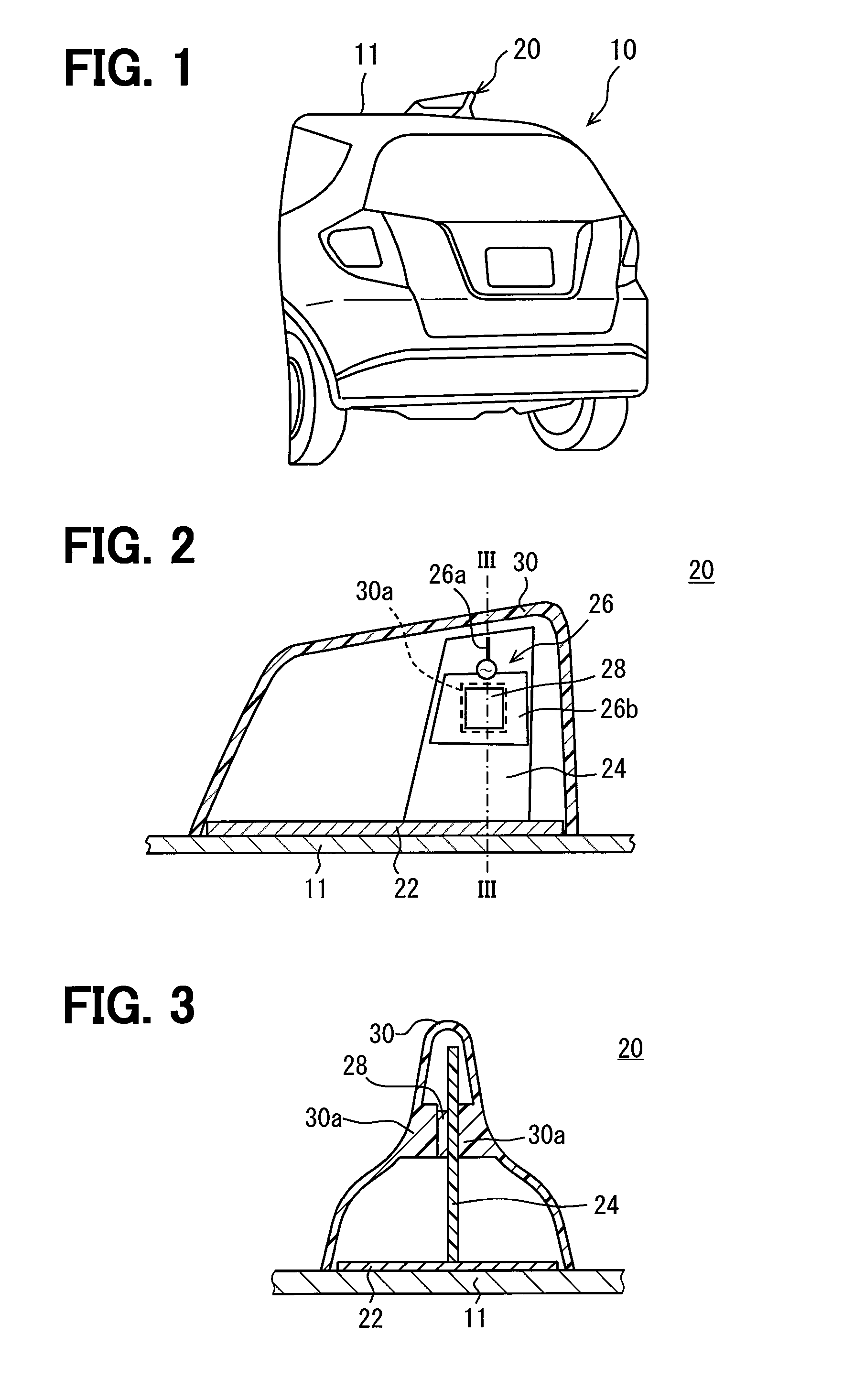
[0027]As shown in FIG. 1, a vehicle-mounted antenna device 20 according to the present embodiment is mounted on a roof 11 of a vehicle 10. The vehicle-mounted antenna device 20 is what is called a shark fin antenna device. The vehicle-mounted antenna device 20 is hereinafter simply referred to as the antenna device 20.

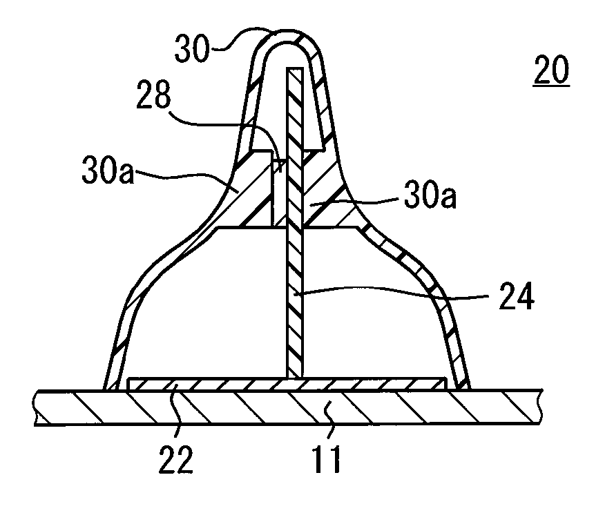
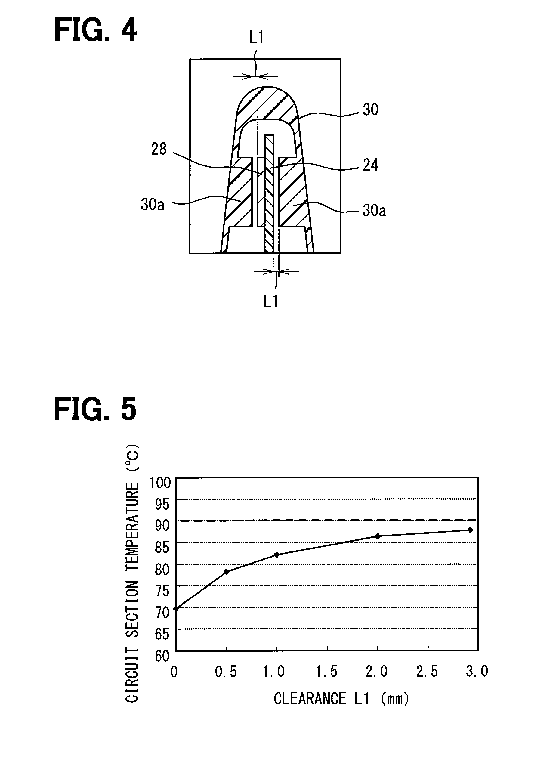
[0028]As shown in FIGS. 2 and 3, the antenna device 20 mainly includes a base 22, a board 24 stood on the base 22, a circuit section 28 implemented on the board 24, and a housing 30 made of a resin material and forming a projection of a vehicle outer shape.

[0029]The base 22 is used to fix the board 24 to the vehicle 10 and mounted on the roof 11 through a mounting member which is not shown. The base 22 has a flat plate shape and is mounted almost parallel to the roof 11. Further, when the base 22 is made of a metal material and electrically connected to the roof 11 through the mounting member, the base 22 serves as a ground plane. Whether or not...

second embodiment

[0045](Second Embodiment)

[0046]Descriptions of the same structures of the present embodiment as those of the antenna device 20 of the above-described embodiment are omitted.

[0047]As exemplified in FIG. 7, according to the present embodiment, a heat transfer member 32 made of a material having a thermal conductivity higher than that of air is interposed between the circuit section 28 and the housing 30 to provide a heat transfer path. In particular, in an example shown in FIG. 7, the heat transfer member 32 is a ring-shaped member made of rubber, which is an elastic member. The ring-shaped member as the heat transfer member 32 is in contact with and fixed by adhesive or the like to each of the circuit section 28 and the opposite region of the board 24 to the region where the circuit section 28 is implemented.

[0048]When the heat transfer member 32 is interposed between the circuit section 28 and the housing 30, the heat dissipation efficiency can be improved compared to when the heat ...

third embodiment

[0050](Third Embodiment)

[0051]Descriptions of the same structures of the present embodiment as those of the antenna device 20 of the above-described embodiment are omitted.

[0052]As exemplified in FIGS. 9 and 10, according to the present embodiment, the board 24 is a flexible board. Further, the housing 30 has a guide portion 34 for allowing the board 24 to be placed along its inner surface. Out of the opposite surface of the board 24 to the surface where the circuit section 28 is implemented, at least the opposite region of the board 24 to the region where the circuit section 28 is implemented is in contact with the inner surface of the housing 30. It is noted that a character 36 in FIG. 9 represents a connector.

[0053]When the board 24 is a flexible board as described above, the opposite region of the board 24 to the region where the circuit section 28 is implemented can be brought in contact with the inner surface of the housing 30 without the thickened portion 30a. Thus, a heat tr...


PUM


Abstract

A vehicle-mounted antenna device includes a base, a board, a circuit section, and a housing. The base is mountable on a roof of a vehicle. The board has an antenna element section and is stood on the base. The circuit section is implemented on the board and serves as at least part of a wireless communication circuit electrically connected to the antenna element section. The housing is made of a resin material and forms a projection of an outer shape of the vehicle. The board and the circuit section are located in space formed by the base and the housing. A heat transfer path having a thermal conductivity higher than that of air is formed between the circuit section and the housing without passing the base.

Description

CROSS REFERENCE TO RELATED APPLICATIONS[0001]This application is a U.S. National Phase Application under 35 U.S.C. 371 of International Application No. PCT / JP2013 / 003860 filed on Jun. 20, 2013 and published in Japanese as WO 2014 / 033995 A1 on Mar. 6, 2014. This application is based on and claims the benefit of priority from Japanese Patent Application No. 2012-193251 filed on Sep. 3, 2012. The entire disclosures of all of the above applications are incorporated herein by reference.TECHNICAL FIELD[0002]The present disclosure relates to vehicle-mounted antenna devices and in particular, relates to a vehicle-mounted antenna device used for vehicle-to-vehicle communication and vehicle-to-road-side communication.BACKGROUND ART[0003]As disclosed in a patent literature 1, an antenna device is known that has a GPS antenna, a DTV antenna, and a radio antenna which are placed in space formed by an antenna base (hereinafter referred to as a base) and an antenna cover (hereinafter referred to a...

Claims


Application Information

Patent Timeline
Patent Type & Authority Patents(United States)
IPC IPC(8): H01Q1/32H01Q1/42H05K1/02H05K1/18H05K5/00H01Q9/42H01Q1/02
CPCH01Q1/3275H01Q1/02H01Q1/42H01Q9/42H05K1/0203H05K1/028H05K1/181H05K5/003H05K2201/10098
Inventor SUGIMOTO, YUJIMATSUI, HIROHITOSUZUKI, TADAOKATAOKA, RYOHEI
Owner DENSO CORP
Why Eureka
Try Eureka