Vehicle-mounted antenna device
a technology of antenna devices and antennas, which is applied in the direction of resonant antennas, printed circuit non-printed electric components association, electrical apparatus casings/cabinets/drawers, etc., can solve the problems of increased temperature, increased transmission loss, and loss of transmission cables, so as to reduce the degradation of circuit section performance caused by temperature increase, the effect of radiating sun radiation and transfer to the circuit section
- Summary
- Abstract
- Description
- Claims
- Application Information
AI Technical Summary
Benefits of technology
Problems solved by technology
Method used
Image
Examples
first embodiment
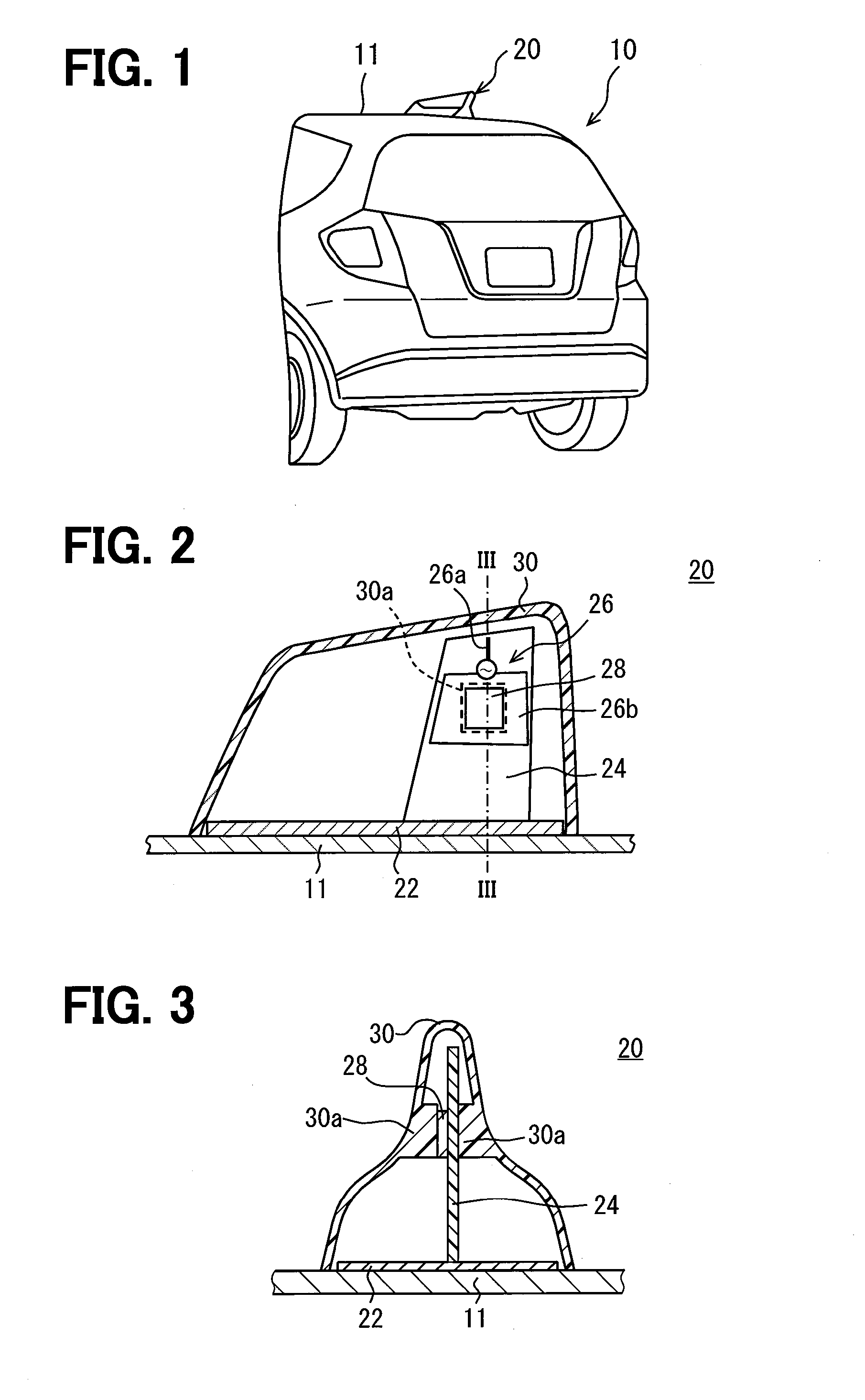
[0026]As shown in FIG. 1, a vehicle-mounted antenna device 20 according to the present embodiment is mounted on a roof 11 of a vehicle 10. The vehicle-mounted antenna device 20 is what is called a shark fin antenna device. The vehicle-mounted antenna device 20 is hereinafter simply referred to as the antenna device 20.
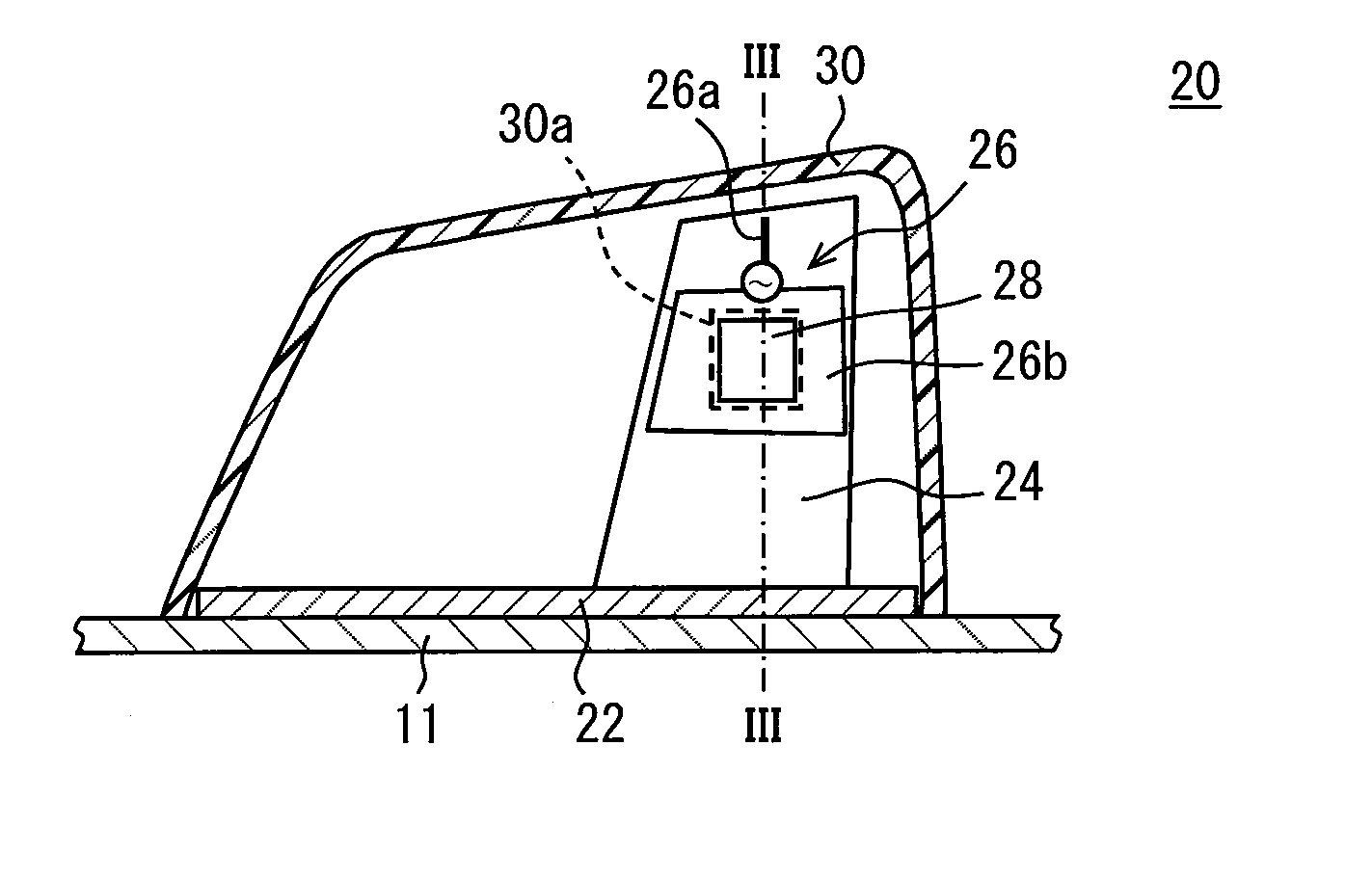
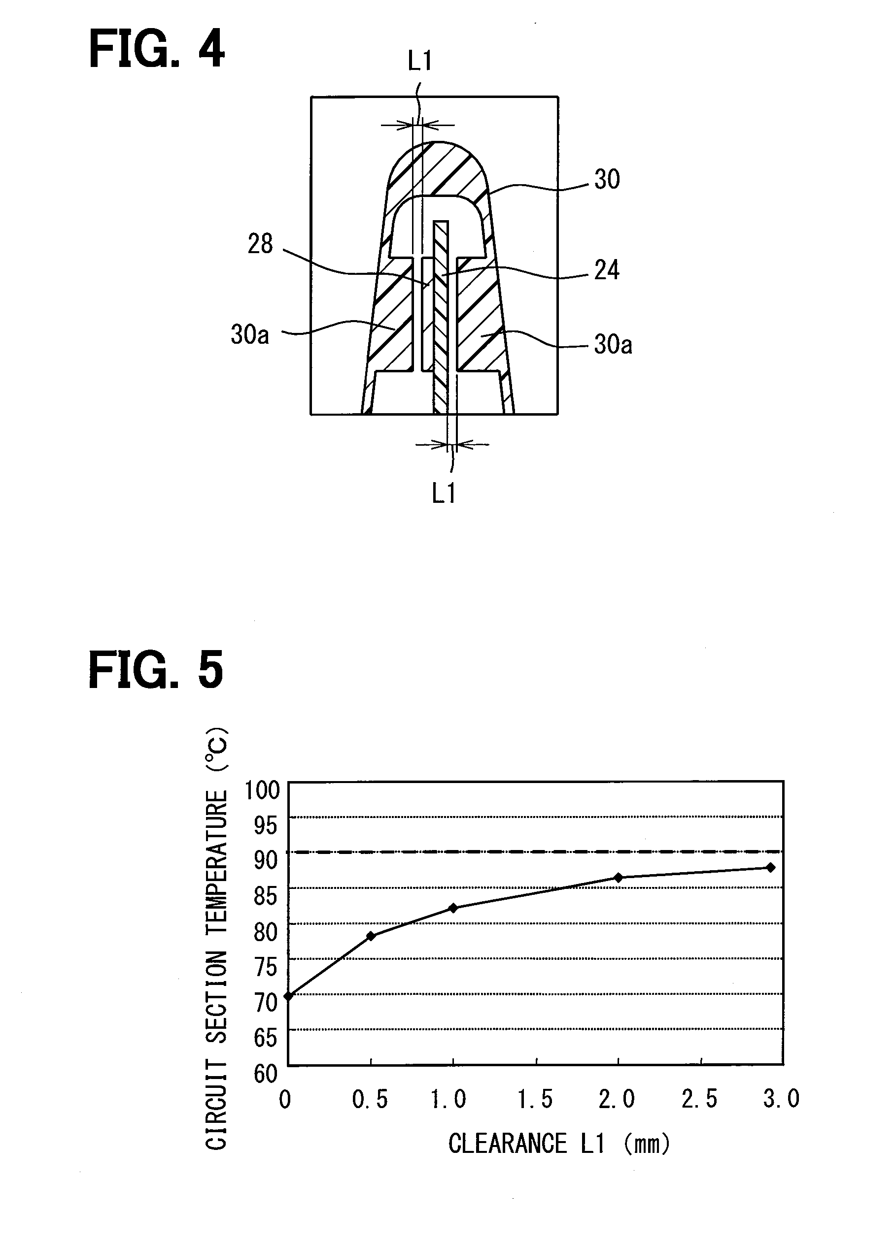
[0027]As shown in FIGS. 2 and 3, the antenna device 20 mainly includes a base 22, a board 24 stood on the base 22, a circuit section 28 implemented on the board 24, and a housing 30 made of a resin material and forming a projection of a vehicle outer shape.
[0028]The base 22 is used to fix the board 24 to the vehicle 10 and mounted on the roof 11 through a mounting member which is not shown. The base 22 has a flat plate shape and is mounted almost parallel to the roof 11. Further, when the base 22 is made of a metal material and electrically connected to the roof 11 through the mounting member, the base 22 serves as a ground plane. Whether or not it is used as a ground ...
second embodiment
[0044]Descriptions of the same structures of the present embodiment as those of the antenna device 20 of the above-described embodiment are omitted.
[0045]As exemplified in FIG. 7, according to the present embodiment, a heat transfer member 32 made of a material having a thermal conductivity higher than that of air is interposed between the circuit section 28 and the housing 30 to provide a heat transfer path. In particular, in an example shown in FIG. 7, the heat transfer member 32 is a ring-shaped member made of rubber, which is an elastic member. The ring-shaped member as the heat transfer member 32 is in contact with and fixed by adhesive or the like to each of the circuit section 28 and the opposite region of the board 24 to the region where the circuit section 28 is implemented.
[0046]When the heat transfer member 32 is interposed between the circuit section 28 and the housing 30, the heat dissipation efficiency can be improved compared to when the heat of the circuit section 28...
third embodiment
[0048]Descriptions of the same structures of the present embodiment as those of the antenna device 20 of the above-described embodiment are omitted.
[0049]As exemplified in FIGS. 9 and 10, according to the present embodiment, the board 24 is a flexible board. Further, the housing 30 has a guide portion 34 for allowing the board 24 to be placed along its inner surface. Out of the opposite surface of the board 24 to the surface where the circuit section 28 is implemented, at least the opposite region of the board 24 to the region where the circuit section 28 is implemented is in contact with the inner surface of the housing 30. It is noted that a character 36 in FIG. 9 represents a connector.
[0050]When the board 24 is a flexible board as described above, the opposite region of the board 24 to the region where the circuit section 28 is implemented can be brought in contact with the inner surface of the housing 30 without the thickened portion 30a. Thus, a heat transfer path is formed be...
PUM
 Abstract
Description
Claims
Application Information
 - R&D
- Intellectual Property
- Life Sciences
- Materials
- Tech Scout
- Unparalleled Data Quality
- Higher Quality Content
- 60% Fewer Hallucinations
Browse by: Latest US Patents, China's latest patents, Technical Efficacy Thesaurus, Application Domain, Technology Topic, Popular Technical Reports.
© 2025 PatSnap. All rights reserved.Legal|Privacy policy|Modern Slavery Act Transparency Statement|Sitemap|About US| Contact US: help@patsnap.com


