Optical device and a making method thereof

a technology of optical devices and making methods, applied in the direction of glass optical fibres, cladded optical fibres, instruments, etc., can solve the problems of increasing the diameter of coils, increasing the size of dispersion compensators accordingly, and achieving large bending losses, reducing bending losses, and large transmission losses

Inactive Publication Date: 2006-05-09
SUMITOMO ELECTRIC IND LTD
View PDF42 Cites 2 Cited by
  • Summary
  • Abstract
  • Description
  • Claims
  • Application Information

AI Technical Summary

Benefits of technology

[0007]Nevertheless, since a wide-band DCF has a large bending loss in general, it may yield a large transmission loss in the 1.55-μm band, i.e., transmission wavelength band, when formed into a coil having a small diameter. This bending loss can be reduced when the coil has a larger diameter so that its number of turns is reduced. Increasing the coil diameter, however, is unfavorable in that the dispersion compensator accordingly becomes larger.
[0008]Also, the dispersion compensator is often used together with an optical amplifier using an erbium-doped optical fiber. In this case, the temperature of the dispersion compensator increases due to the heat from a pumping laser within the optical amplifier, so that the bobbin may thermally expand. As a result, distortions may occur in the wound wide-band DCF, thereby increasing the transmission loss. Using a material with less thermal expansion in the bobbin can reduce the transmission loss in such a high-temperature environment. However, materials having low coefficients of thermal expansion, such as silica glass, ceramics, special alloys, and the like, are hard to process or expensive.
[0009]Therefore, it is an object of the present invention to provide an optical assembly accommodating therein a long optical fiber in a compact fashion, which yields less increase in transmission loss upon such bending or heat; and a method of making the same.

Problems solved by technology

Nevertheless, since a wide-band DCF has a large bending loss in general, it may yield a large transmission loss in the 1.55-μm band, i.e., transmission wavelength band, when formed into a coil having a small diameter.
Increasing the coil diameter, however, is unfavorable in that the dispersion compensator accordingly becomes larger.
As a result, distortions may occur in the wound wide-band DCF, thereby increasing the transmission loss.
However, materials having low coefficients of thermal expansion, such as silica glass, ceramics, special alloys, and the like, are hard to process or expensive.

Method used


Image

  • Optical device and a making method thereof
  • Optical device and a making method thereof
  • Optical device and a making method thereof

Examples


example a

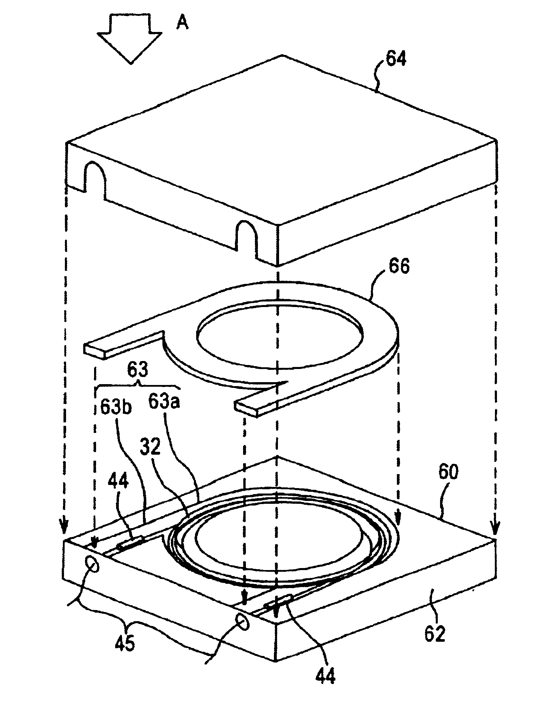
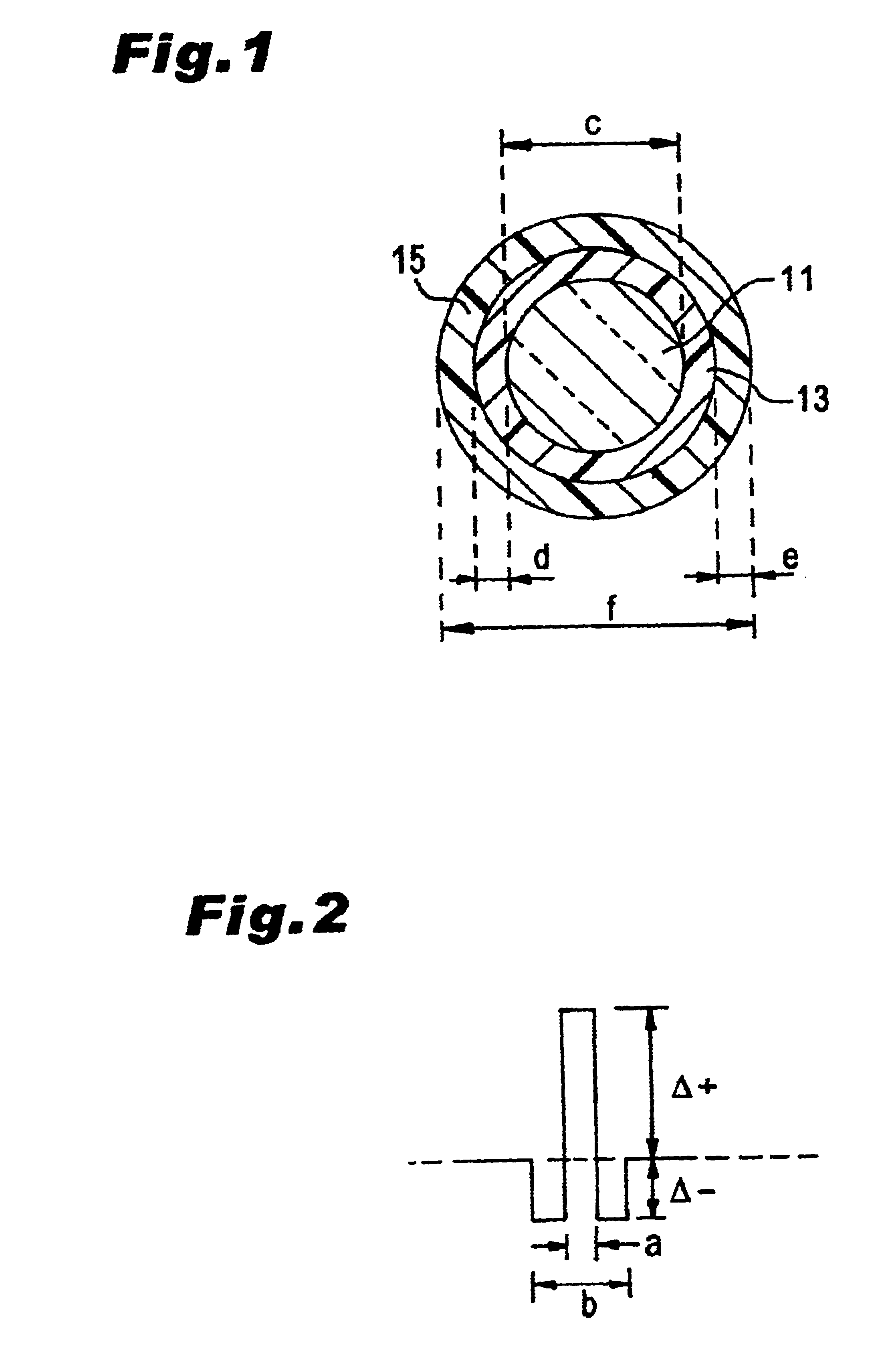
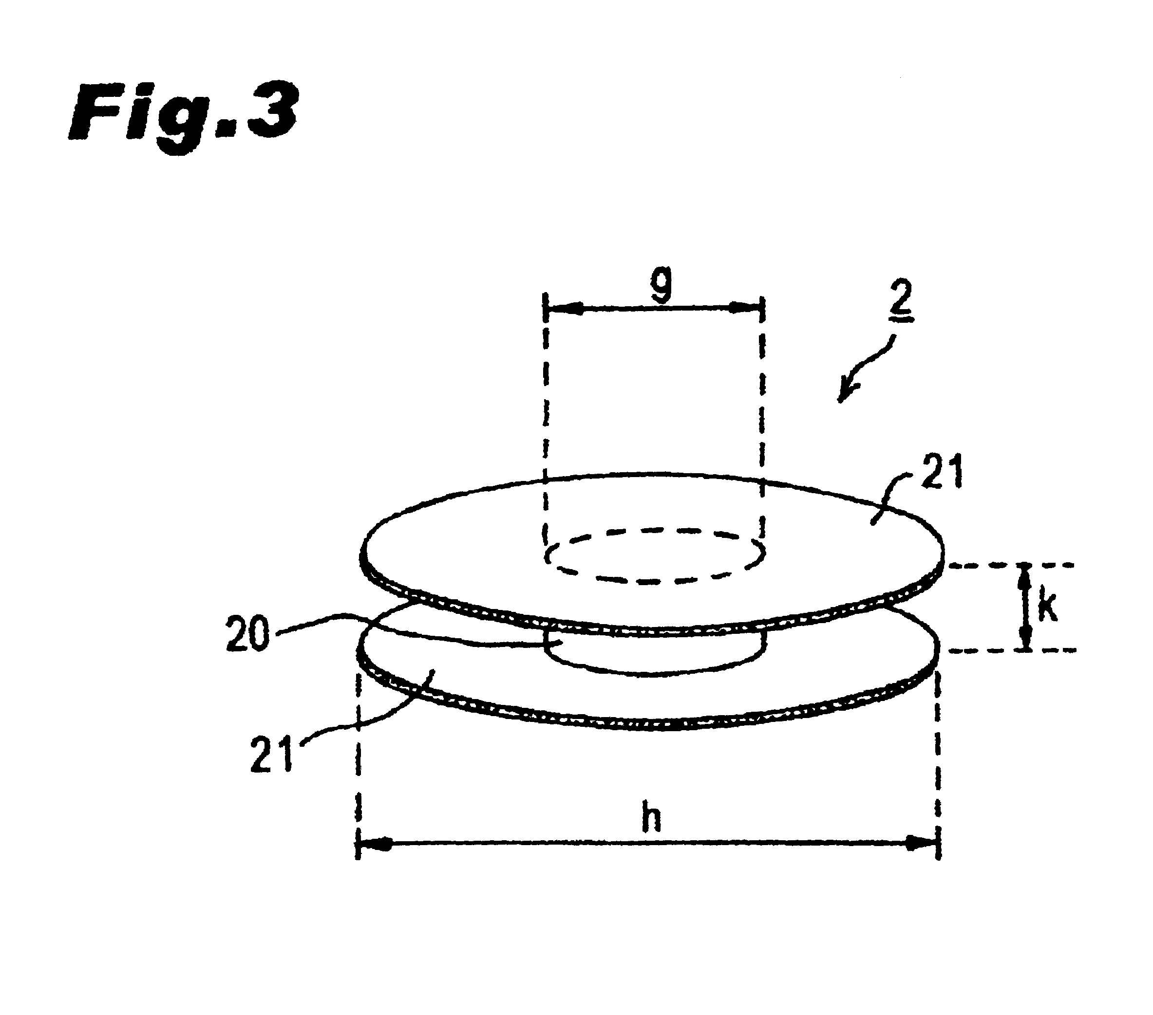
[0154]Around a bobbin 2 made of aluminum in which g=120 mm and k=45 mm, about 90 plies of a DCF having a length of 9 km, the form shown in FIG. 1, and the refractive index profile shown in FIG. 2 were wound with a winding pitch of 0.28 mm at each of two kinds of take-up tensions of 50 gf and 70 gf, whereby two kinds of dispersion compensators were produced. This DCF has the specific characteristics shown in the following Table.

[0155]

CharacteristicsValuesΔ+ 2.5%Δ−−0.5%a2.54 μmb7.26 μmc 100 μmd  20 μme  20 μmf 180 μmYoung's modulus of primary0.06 kgf / mm2coating layer 13Young's modulus of secondary65 kgf / mm2coating layer 15

[0156]FIG. 25 is a graph plotting thus obtained two kinds of dispersion compensators in terms of take-up tension and transmission loss value at a wavelength of 1.55 μm which are indicated by the abscissa and the ordinate, respectively. The broken line indicates the transmission loss value (0.53 dB / km) of the DCF at a wavelength of 1.55 μm in the state wound around a ...

example b

[0157]Around a bobbin 2 made of aluminum in which g=60 mm and k=45 mm, about 190 plies of a DCF, identical to that of Example A, having a length of 13 km were wound with a winding pitch of 0.28 mm at each of three kinds of take-up tensions of 20 gf, 25 gf, and 50 gf, whereby three kinds of dispersion compensators were produced.

[0158]FIG. 26 is a graph plotting thus obtained three kinds of dispersion compensators in terms of take-up tension and transmission loss value at a wavelength of 1.55 μm which are indicated by the abscissa and the ordinate, respectively. The broken line is a transmission loss value shown for comparison as with FIG. 25. The transmission value was 2.54 dB / km and 1.05 dB / km when the take-up tension was 50 gf and 25 gf, respectively, thereby becoming smaller as the take-up tension was lower. At the take-up tension of 20 gf, however, the transmission loss value increased to 2.95 dB / km. It is assumed to be because the take-up tension was so low that the winding of t...

example c

[0159]Around a bobbin 2 made of aluminum in which g=100 mm and k=18 mm, about 210 plies of a DCF having a length of 8 km and the characteristics shown in the following Table (see FIGS. 1 and 2 for its form and refractive index profile, respectively) were wound with a winding pitch of 0.40 mm at each of four kinds of take-up tensions of 20 gf, 30 gf, 40 gf, and 50 gf, whereby four kinds of dispersion compensators were produced. This DCF has the specific characteristics shown in the following Table.

[0160]

CharacteristicsValueΔ+ 2.1%Δ− −0.35%a2.65 μmb7.58 μmc 110 μmd  20 μme  15 μmf 180 μmYoung's modulus of0.03 kgf / mm2primary coating layer 13Young's modulus of 100 kgf / mm2secondary coating layer15

[0161]FIG. 27 is a graph plotting thus obtained four kinds of dispersion compensators in terms of take-up tension and transmission loss value at a wavelength of 1.55 μm which are indicated by the abscissa and the ordinate, respectively. The broken line also indicates take-up tension and transmis...


PUM


Abstract

After a wide-band DCF is wound around a bobbin to form an optical fiber coil 32, the latter is removed from the bobbin and placed into a bundle state (the state where the increase in transmission loss in the wavelength band of 1.55 μm caused by distortions in winding is reduced by 0.1 dB / km or more) released from distortions in winding. A resin 42 is used as a coil-tidying member so as to secure the optical fiber coil 32 to a storage case 40 at four positions. Both ends of the optical fiber coil 32 are connected to pigtail fibers at fusion-splicing parts 44, respectively. Even when the storage case 40 is closed with a lid after the optical fiber coil 32 is secured to the storage case 40 with the resin 42, there remain interstices within the bundle of the optical fiber coil 32 and a space between the optical fiber coil 32 and the storage case 40. As a result, even when the optical fiber coil 32 in a bundle state is accommodated in the storage case 40, transmission loss and the like would not increase.

Description

RELATED APPLICATION[0001]This application is a divisional of application Ser. No. 09 / 477,561, filed Jan. 4, 2000 now U.S. Pat. No. 6,650,821, which is a continuation-in-part of application Ser. No. 09 / 240,690, filed Feb. 2, 1999 now U.S. Pat. No. 6,546,180.BACKGROUND OF THE INVENTION[0002]1. Field of the Invention[0003]The present invention relates to a coiled optical assembly made of a long optical fiber and a fabricating method for the same; and, in particular, to a dispersion compensator for reducing the wavelength dispersion of an optical fiber transmission line in the wavelength band of 1.55 μm, and a fabricating method for the same.[0004]2. Related Background Art[0005]Long-distance, large-capacity transmission is possible in the wavelength band of 1.55 μm by means of an optical amplifier operable in the wavelength band of 1.55 μm utilizing an optical fiber doped with erbium (Er) which is a rare-earth element. However, when transmission is carried out in the wavelength band of ...

Claims


Application Information

Patent Timeline
Patent Type & Authority Patents(United States)
IPC IPC(8): G02B6/00G02B6/10
CPCG02B6/4457G02B6/02214G02B6/02261Y10T428/2933G02B6/02395G02B6/03627
Inventor KOYANO, YASUSHISASAOKA, EISUKETANAKA, SHIGERUKOBAYASHI, KOHEIONISHI, MASASHITAMANO, KENJIFUJII, TAKASHI
Owner SUMITOMO ELECTRIC IND LTD
Why Eureka
Try Eureka