Disconnect clutch

a technology of disconnection clutch and disconnection plate, which is applied in the direction of fluid-actuated clutches, clutches, non-mechanical actuated clutches, etc., can solve the problems of not allowing for disengagement of accessories, continuous parasitic load placed on the engine, and difficulty in adjusting the cylinder rotation speed

Active Publication Date: 2017-03-14
CATERPILLAR INC
View PDF12 Cites 7 Cited by
  • Summary
  • Abstract
  • Description
  • Claims
  • Application Information

AI Technical Summary

Problems solved by technology

Diesel engines can, from time to time, experience difficulties when starting, particularly in cold ambient temperatures.
One contributing factor is the continuous parasitic loads placed on the engine during startup.
This type of design has structural drawbacks and does not allow for disengagement of accessories during engine idling.

Method used


Image

  • Disconnect clutch
  • Disconnect clutch
  • Disconnect clutch

Examples


Embodiment Construction

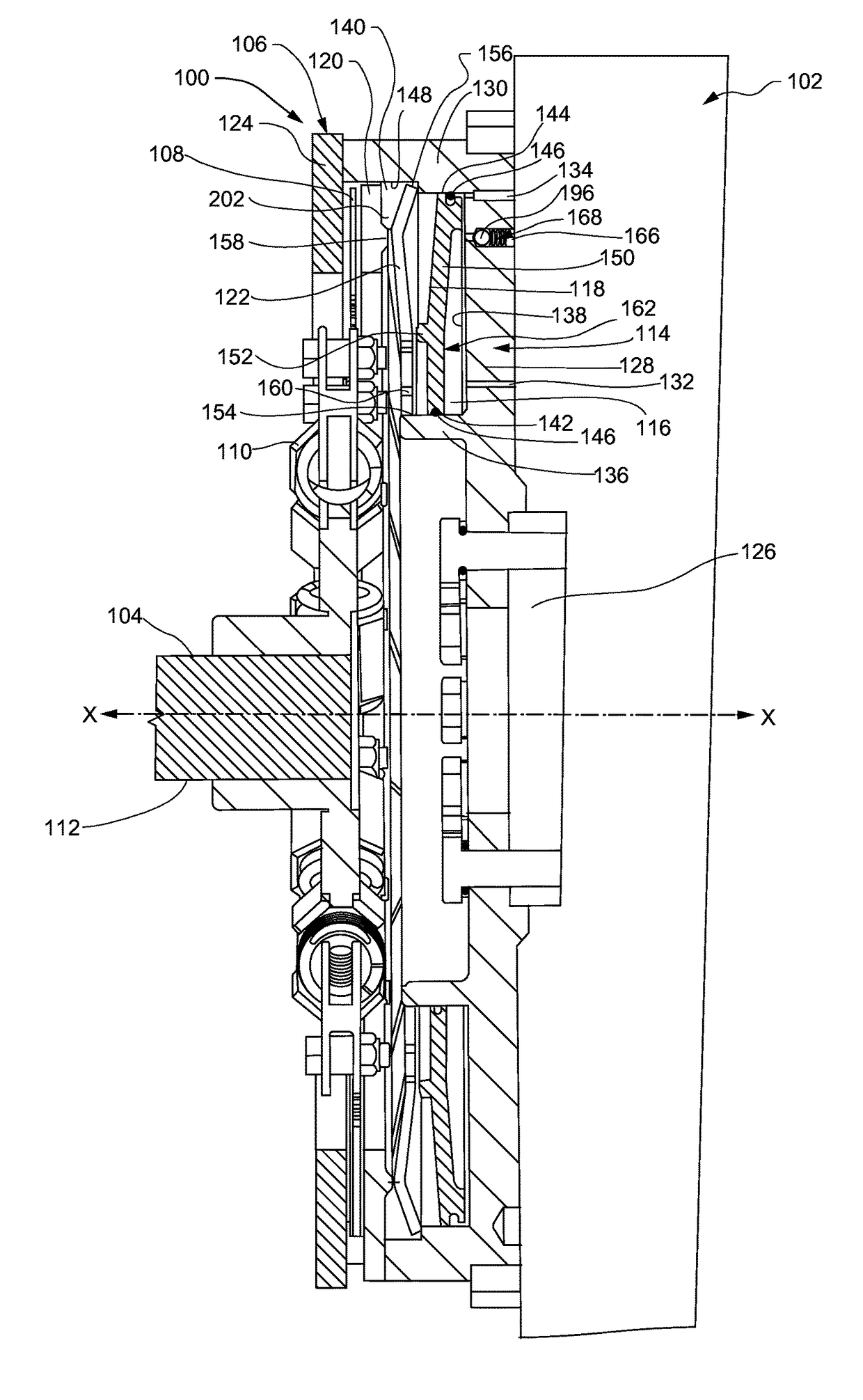
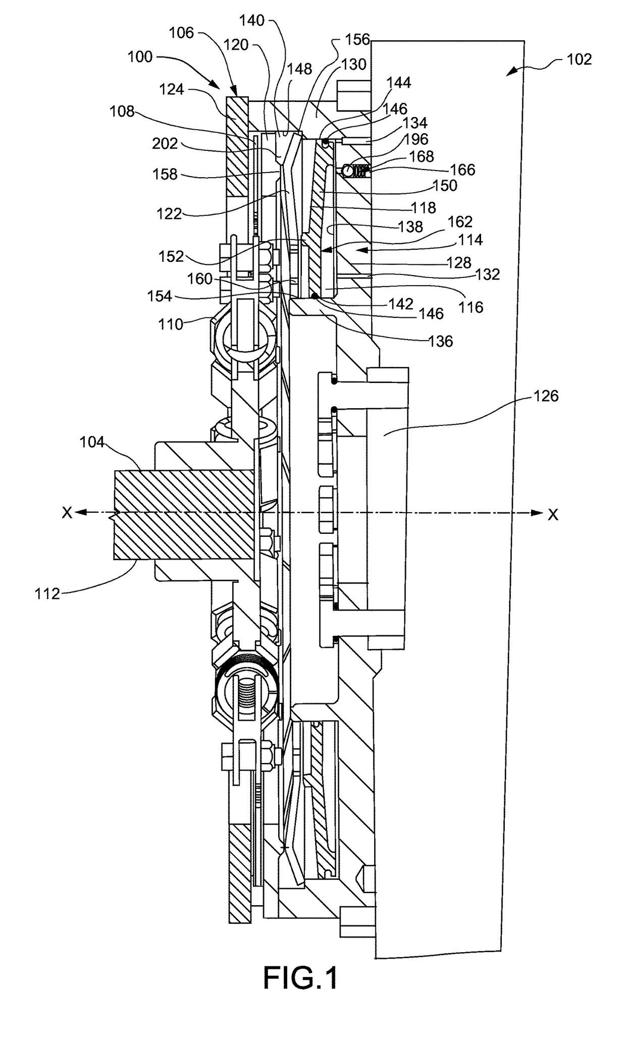
[0015]Referring now to the drawings, and with specific reference to FIG. 1, there is shown a cross-sectional view of an embodiment of a disconnect clutch constructed in accordance with the present disclosure and generally referred to by reference numeral 100. The disconnect clutch 100 is attached to an exemplary engine 102. The disconnect clutch 100 may be attached to at least one parasitic load 104. While the following detailed description and drawings are made with reference to a disconnect clutch 100 for a truck engine 102 or an engine used in mining or construction machines, the teachings of this disclosure may be employed on other types of vehicles.

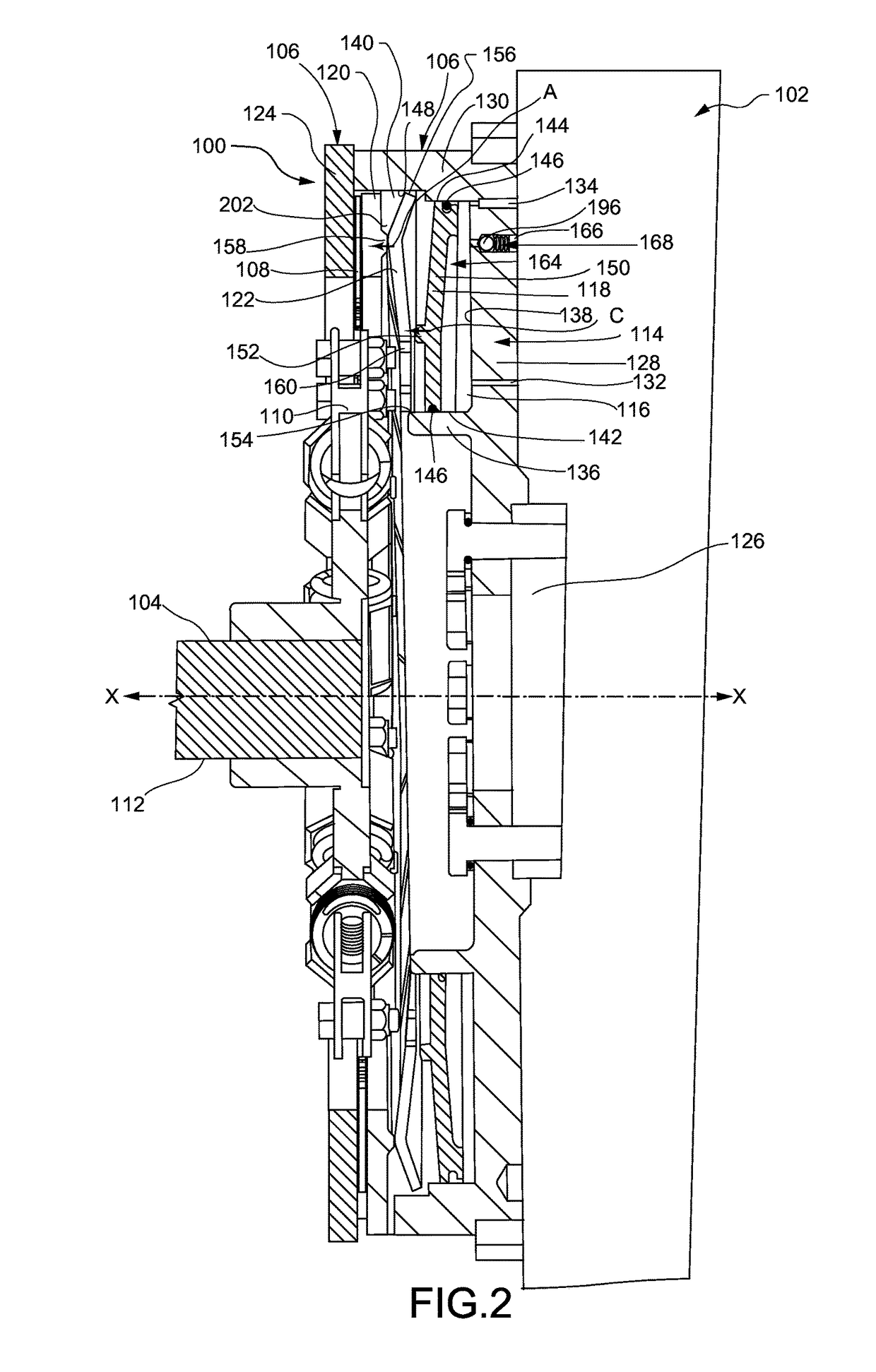
[0016]Turning now to FIGS. 1-3, the disconnect clutch 100 may comprise a flywheel assembly 106, at least one friction plate 108 and a coupling 110.

[0017]The flywheel assembly 106 is rotatable about an X-axis and may include a flywheel 114, a chamber 116, a piston 118, a pressure plate 120, and a lever 122. The flywheel assembly 106 i...


PUM


Abstract

A disconnect clutch and method of controlling the connection of a parasitic load to an engine disposed on a machine is disclosed. The disconnect clutch may comprise a flywheel assembly, a friction plate and a coupling. The flywheel assembly may include a flywheel having a cavity, a chamber, a piston moveable between a contracted position and an expanded position, a pressure plate, a lever, and a coupling operably connected to the friction plate. The flywheel may include an end plate. The chamber may be defined by the flywheel and the piston. The lever may apply an activation force to the pressure plate when the piston is in the expanded position. The friction plate may be attached to and rotatable with the flywheel assembly when the piston is in the expanded position and generally stationary when the piston is in the contracted position.

Description

TECHNICAL FIELD[0001]The present disclosure generally relates to engines and, more particularly, relates to a disconnect clutch for controlling the connection of parasitic loads to engines.BACKGROUND[0002]Diesel engines are used in a wide variety of industrial applications. These engines are known as compression ignition engines because they are internal combustion engines that utilize the heat of compression to ignite the diesel fuel in the combustion chamber of the engine.[0003]Diesel engines can, from time to time, experience difficulties when starting, particularly in cold ambient temperatures. One contributing factor is the continuous parasitic loads placed on the engine during startup.[0004]U.S. Pat. No. 4,708,229, issued on Nov. 24, 1987, discloses a drive that permits engine driven accessories to be momentarily disengaged from the engine during startup. This type of design has structural drawbacks and does not allow for disengagement of accessories during engine idling. A be...

Claims


Application Information

Patent Timeline
Patent Type & Authority Patents(United States)
IPC IPC(8): F16D25/0635F16D25/063F16D25/0638F16D13/58
CPCF16D25/0635F16D25/063F16D25/0638F16D13/583
Inventor ANDERSON, MICHAEL DOUGLASBRINKMEYER, MEGAN ALISSASERGISON, DANIEL P.BROSOWSKE, THOMAS ALANPETERSON, GRANT STEVENCRONIN, MICHAEL G.DERER, RAYMOND B.
Owner CATERPILLAR INC
Why Eureka
Try Eureka