Layer thickness measurement method
a layer thickness and measurement method technology, applied in the field of layer thickness measurement method, can solve the problem of taking a long time for the measurement of the opaque layer thickness
- Summary
- Abstract
- Description
- Claims
- Application Information
AI Technical Summary
Benefits of technology
Problems solved by technology
Method used
Image
Examples
example 1
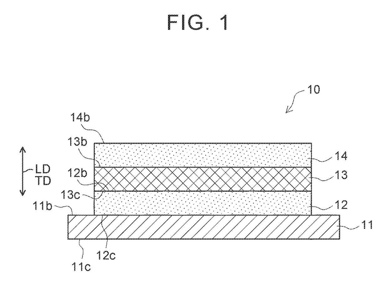
[0051]Hereinafter, Example 1 of the invention will be described with reference to accompanying drawings. An opaque laminated body 10, which is an object to be measured according to this Example 1, will be described first. As illustrated in FIG. 1, the opaque laminated body 10 is an opaque laminated body in which four opaque layers are laminated in their thickness direction TD (vertical direction in FIG. 1). In the opaque laminated body 10, the opaque layers that are adjacent to each other in a laminating direction LD (vertical direction in FIG. 1) have different colors.
[0052]Specifically, the opaque laminated body 10 is a laminated battery material including a current collector 11, a first electrode mixture layer 12, a solid electrolyte layer 13, and a second electrode mixture layer 14 as illustrated in FIG. 1. The current collector 11 is an opaque layer. The first electrode mixture layer 12 is an opaque layer that is laminated on a surface 11b of the current collector 11. The solid...
example 2
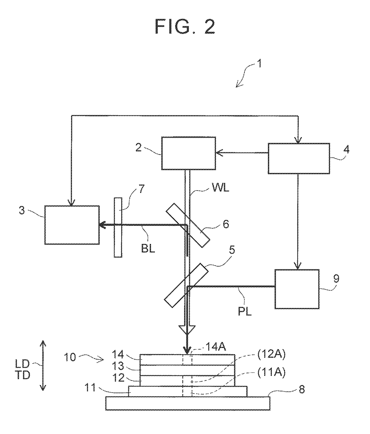
[0076]Hereinafter, Example 2 of the invention will be described with reference to accompanying drawings. This Example 2 differs from Example 1 in that the thickness of every opaque layer constituting the opaque laminated body 10 is grasped and in that the depths of three portions to be removed are measured with regard to each opaque layer and the average value of the measured results is acquired as the thickness of each opaque layer. Example 2 is similar to Example 1 in the other aspects. Accordingly, the following description will focus on the differences from Example 1 while description of the similar aspects is omitted or simplified.
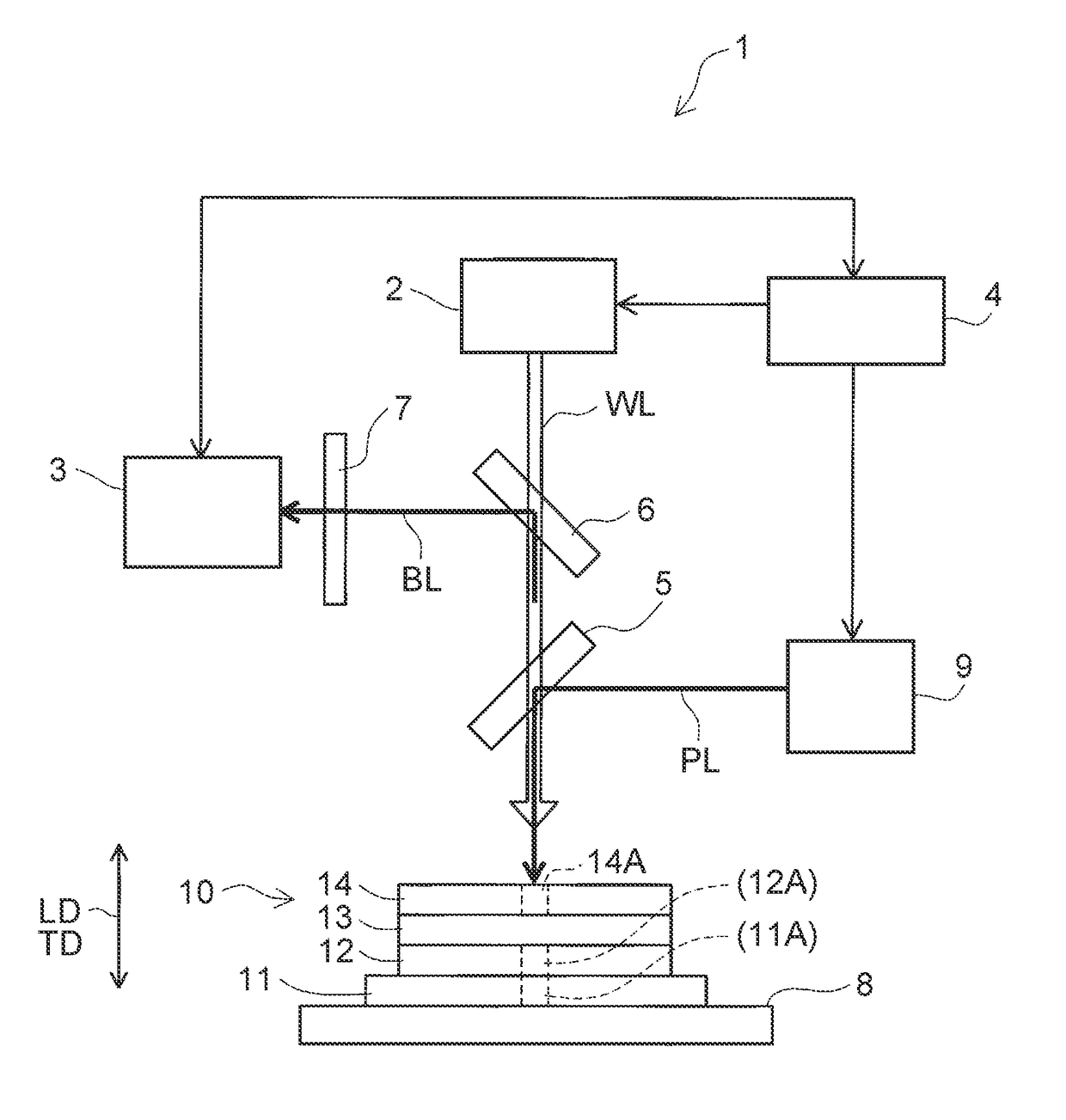
[0077]In this Example 2, the current collector 11 has the columnar portion to be removed 11A that is positioned across the entire thickness of the current collector 11 (refer to FIGS. 2 and 3). This portion to be removed 11A is a region that is to be removed (ablated) by pulse laser PL applying (described later). Likewise, the first electrode mixture ...
PUM
 Abstract
Description
Claims
Application Information
 - R&D Engineer
- R&D Manager
- IP Professional
- Industry Leading Data Capabilities
- Powerful AI technology
- Patent DNA Extraction
Browse by: Latest US Patents, China's latest patents, Technical Efficacy Thesaurus, Application Domain, Technology Topic, Popular Technical Reports.
© 2024 PatSnap. All rights reserved.Legal|Privacy policy|Modern Slavery Act Transparency Statement|Sitemap|About US| Contact US: help@patsnap.com


