Liquid ejecting head and liquid ejecting apparatus
a liquid ejecting and liquid ejecting technology, which is applied in the direction of printing and inking apparatus, etc., can solve the problems of lowering the printing property of ink jet printers, prone to stagnation of ink in this angled corner, and prone to stay in the angled corner of bubbles generated inside the channel
- Summary
- Abstract
- Description
- Claims
- Application Information
AI Technical Summary
Benefits of technology
Problems solved by technology
Method used
Image
Examples
first embodiment
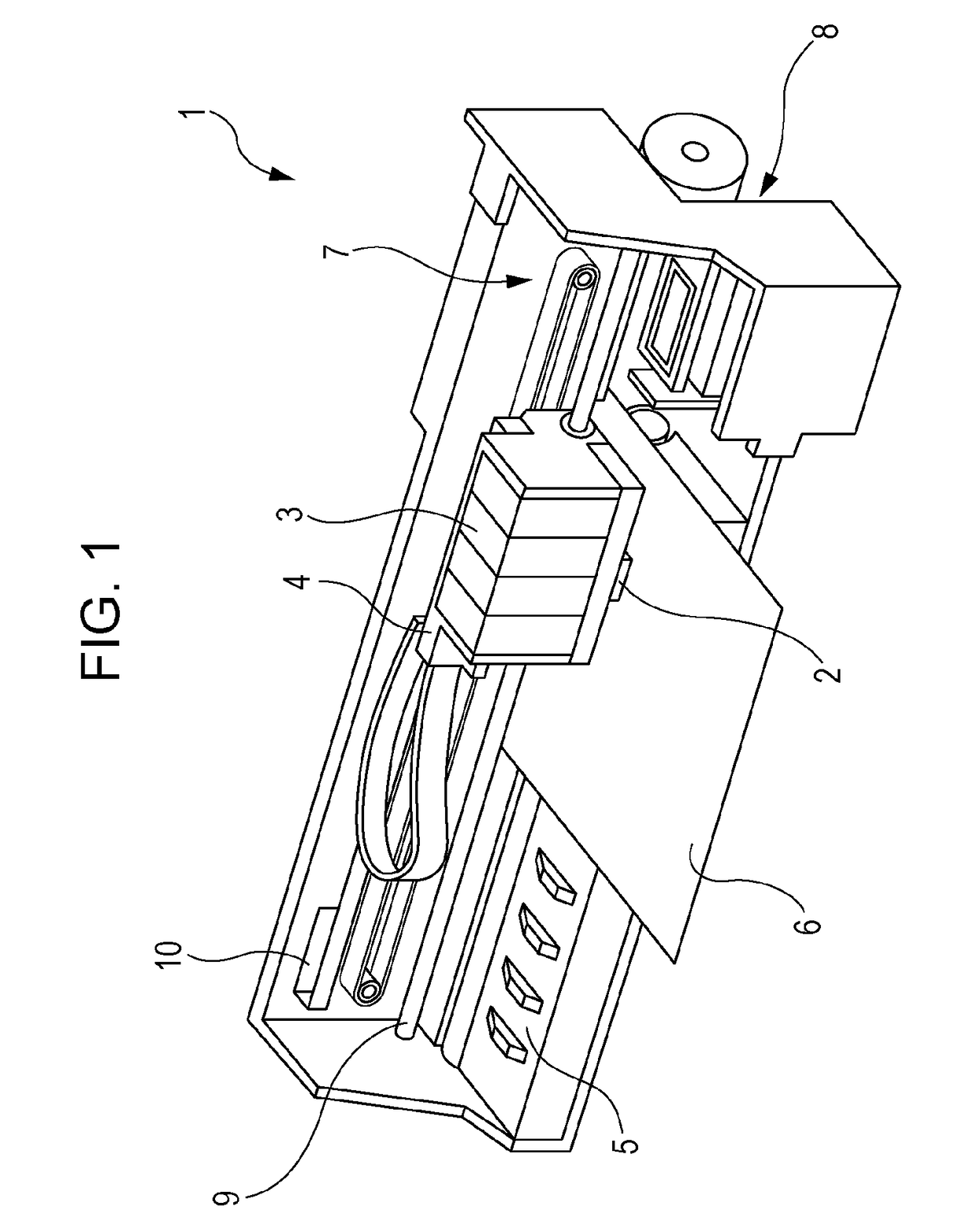
[0036]An ink jet recording apparatus 1 illustrated in FIG. 1 is an exemplary liquid ejecting apparatus. This ink jet recording apparatus 1 is referred to below as a printer 1.
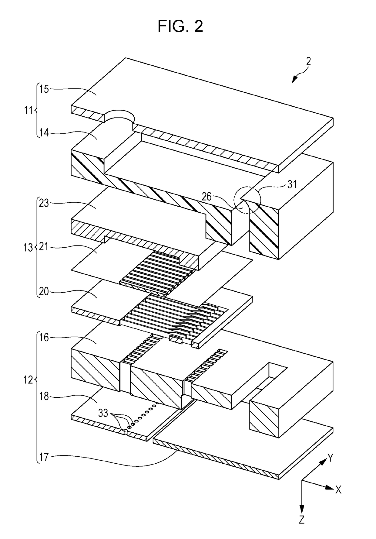
[0037]The printer 1 includes an ink jet recording head unit 2, which is an exemplary liquid ejecting head; the ink jet recording head unit 2 is referred to below as a head unit 2. The head unit 2 can eject liquid, more specifically ink, in droplet form. In the printer 1, the head unit 2 and ink cartridges 3 are mounted in a carriage 4. A platen 5 is disposed below the head unit 2. A carriage moving mechanism 7 moves the carriage 4 in sheet width directions of a recording sheet 6 that is a target on which ink ejected from nozzles 32 is to land. The sheet width directions are main-scanning directions in which the head unit 2 reciprocates. A sheet feeding mechanism 8 transports the recording sheet 6 in a sheet feeding direction, which is orthogonal to the sheet width directions. The sheet feeding direction is a su...
second embodiment
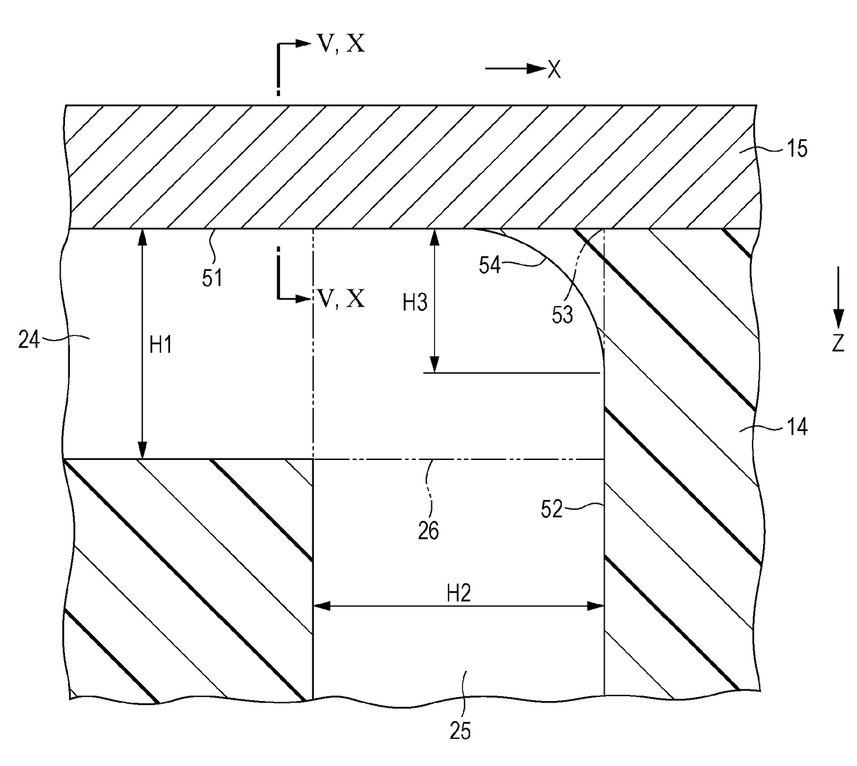
[0068]FIG. 8 is an enlarged sectional view of a curved section 26 in a second embodiment of the invention. With reference to FIG. 8, a head unit 2 in the second embodiment will be described. Constituent elements that are the same as in the first embodiment are denoted by the same reference characters and will not be described.
[0069]Referring to FIG. 8, the cover section 31 in the second embodiment has a wall 54 with a flat surface.
[0070]In addition to the effect of the first embodiment, the head unit 2 in the second embodiment produces an effect that it is possible to control the shape of the cover section 31 easily. Since the wall 54 in the cover section 31 in the first embodiment has a curved surface whose orientation gradually changes, it may be difficult to reliably form the wall 54 and measure this shape. In contrast, the wall 54 in the cover section 31 in the second embodiment has a flat surface, it is possible to form the wall 54 accurately in a manufacturing process and meas...
modification 1
[0072]FIG. 9 is an enlarged sectional view of a curved section 26 in modification 1 of the first and second embodiments. In the first and second embodiments, the wall 54 in the cover section 31 has a single surface as illustrated in FIG. 4; however, this configuration is exemplary. A head unit 2 in modification 1 will be described below. Constituent elements that are the same as in the first embodiment are denoted by the same reference characters and will not be described.
[0073]As illustrated in FIG. 9, a wall 54 in the cover section 31 in modification 1 has two surfaces. One of the surfaces of the wall 54 in the cover section 31 intersects the X direction, whereas the other one thereof intersects the Z direction. Examples of the combination of the surfaces include the combination of curved surfaces, the combination of flat surfaces, and the combination of curved and flat surfaces. The wall 54 in the cover section 31 may have three or more surfaces.
[0074]In addition to the effects o...
PUM
 Abstract
Description
Claims
Application Information
 - R&D
- Intellectual Property
- Life Sciences
- Materials
- Tech Scout
- Unparalleled Data Quality
- Higher Quality Content
- 60% Fewer Hallucinations
Browse by: Latest US Patents, China's latest patents, Technical Efficacy Thesaurus, Application Domain, Technology Topic, Popular Technical Reports.
© 2025 PatSnap. All rights reserved.Legal|Privacy policy|Modern Slavery Act Transparency Statement|Sitemap|About US| Contact US: help@patsnap.com


