Ceiling fan

a ceiling fan and fan body technology, applied in the field of ceiling fans, can solve the problems of reducing economic gains, requiring a lot of work and time in assembly of ceiling fans, and causing vibration and abnormal sounds, so as to save man-hours, facilitate and stably be assembled, rotate smoothly and steadily

Active Publication Date: 2017-03-28
YOUNGO
View PDF3 Cites 10 Cited by
  • Summary
  • Abstract
  • Description
  • Claims
  • Application Information

AI Technical Summary

Benefits of technology

[0008]The objective of this invention is to offer a ceiling fan whose blades can be secured on a motor easily and stably and rotated smoothly and steadily. Further, during assembly of the blades, fine adjustment can be done to respective assembly structure for overcoming errors caused by tolerance. This invention is able to shorten man-hour in assembly, heighten assembly efficiency, increase economic benefits, lower manufacturing cost and enhance market competitiveness.
[0010]By so designing, the blades of the ceiling fan of this invention can easily and stably be assembled on the fixed seats via the pressing plates that are secured with the blades. Moreover, in the process of assembling and locking members, the mutual relative positions of the members can be fine adjusted so as to overcome errors caused by tolerance to enable the blades to be fixed on the motor quickly and stably and rotated smoothly and steadily. As can be understood from the above description, this invention is able to save man-hour in assembly, heighten assembly effect and increase economic gains. Further, the pressing plates of this invention are small in area so the pressing plates can be processed and made up by small-sized forming molds, thus able to lower manufacturing cost and enhance market competitiveness.

Problems solved by technology

However, after long-term use of the conventional ceiling fan and in the process of researching and developing ceiling fans, the inventor of this invention found that the blade assembly structure of the conventional ceiling fan can hardly lock and fix the blades 2 stably on the motor 1 and as a result, when the conventional ceiling fan is operated to rotate, the blades 2 are apt to sway, and the combination parts of the blades 2 and the motor 1 will produce vibration and give out abnormal sounds.
Further, slight tolerance between the threaded cylinders 3 and the insert holes 5 makes it hard to have the insert holes 5 simultaneously aligned to the threaded cylinders 3 in a process of assembly of the ceiling fan, thus difficult in combining the blades 2 on the motor 1, taking a lot of work and time in assembly of the ceiling fan and hence lowering economic gains.
Furthermore, the protruding threaded cylinders 3 at the outer circumferential side of the motor 1 must be made up by large-sized forming molds, rendering difficult in processing, high in manufacturing cost and thus unable to enhance market competitiveness.

Method used


Image

  • Ceiling fan
  • Ceiling fan
  • Ceiling fan

Examples


Embodiment Construction

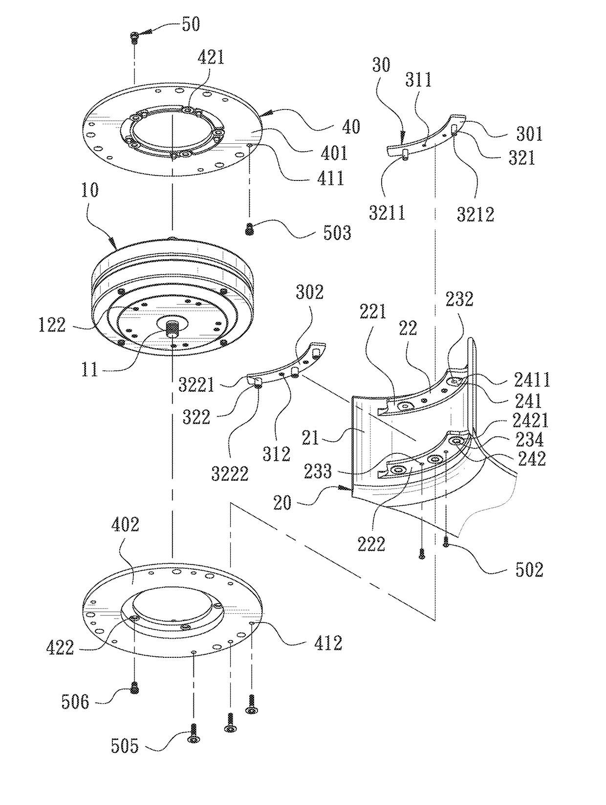
[0020]A preferred embodiment of a ceiling fan in the present invention, as shown in FIGS. 3-8, includes a motor 10, at least one fixed seat 40, a plurality of blades 20, a plurality of pressing plates 30 and a plurality of locking fasteners 50 as main components combined together.

[0021]The motor 10 is formed with a shaft rod 11 axially positioned in the center of the motor 10, and the motor 10 can be rotated relative to the shaft rod 11. The motor 10 is provided with a plurality of first threaded holes 121 and second threaded holes 122, and the first threaded holes 121 corresponding to the shaft rod 11 are spaced apart and annularly positioned at the topside of the motor 10, while the second threaded holes 122 corresponding to the shaft rod 11 are spaced apart and annularly formed at the underside of the motor 10.

[0022]The fixed seat 40 is correspondingly combined with the motor 10. In this invention, there are two fixed seats 40 respectively and correspondingly disposed at the tops...


PUM


Abstract

A ceiling fan includes a motor and plural blades. The motor has its topside and underside respectively secured with a fixed seat, which has its inner side formed with two protruding edges spaced apart and respectively having a pressing plate fixed thereon. The pressing plates are correspondingly combined with the fixed seats so that the blades can be firmly combined with the fixed seats via the pressing plates. The pressing plates can easily be processed and made by small-sized forming molds, able to lower manufacturing cost, and the blades of this invention can be secured on the motor quickly and stably and driven to rotate smoothly and steadily. Further, during assembly of the blades, fine adjustment can be done to respective assembly structure for overcoming errors caused by tolerance. To sum up, this invention is able to shorten man-hour in assembly, enhance assembly efficiency and increase economic gains.

Description

BACKGROUND OF THE INVENTION[0001]1. Field of the Invention[0002]This invention relates to a ceiling fan.[0003]2. Description of the Prior Art[0004]A commonly seen ceiling fan generally includes a motor and a plurality of blades. The blades are firmly combined with the motor by means of fixing members provided on the outer casing of the motor.[0005]As illustrated in FIGS. 1-2, a conventional ceiling fan, as disclosed in a U.S. Pat. No. 7,481,626, includes a motor 1 and a plurality of blades 2. The motor 1 has its outer circumferential side formed with a plurality of threaded cylinders 3, while each blade 2 has its inner side formed with plural protruding edges 4 respectively bored with plural insert holes 5 that correspond to the threaded cylinders 3, and the location and size of the insert holes 5 can be exactly combined and fixed with the threaded cylinders 3. Further, a plurality of locking fasteners 6 are provided to be respectively inserted through the insert holes 5 and threada...

Claims


Application Information

Patent Timeline
Patent Type & Authority Patents(United States)
IPC IPC(8): F04D29/34F04D19/00F04D25/08
CPCF04D25/088F04D29/34F04D19/002
Inventor WANG, CLIFF
Owner YOUNGO
Why Eureka
Try Eureka