Super-oscillatory lens device

a lens device and optical lens technology, applied in the field of super-oscillatory lens devices and methods, can solve the problems of difficult to achieve the image processing process compared with conventional far-field optics, and achieve the effects of small depth of focus, small aperture, and stability

Active Publication Date: 2017-03-28
UNIV OF SOUTHAMPTON
View PDF11 Cites 5 Cited by
  • Summary
  • Abstract
  • Description
  • Claims
  • Application Information

AI Technical Summary

Benefits of technology

[0015]Another significant feature is the ability to generate a very small focus, below the diffraction limit, in a relatively large dark region around it is of great advantage for imaging applications.
[0016]A still further significant feature is that the elongate needle-shaped focus provides the pencil beam which is generally desired for cutting, drilling and related materials processing applications. The needle-shaped focus from the super-oscillatory lens provides a pencil-like beam at the sub-diffraction limit scale. Relevant types of materials processing include lithography to expose photo-resist, machining to remove material (e.g. drilling of vias, drilling of pits, for example by pulsed laser ablation), welding to melt parts together (e.g. bonding of polymer parts in microfluidic devices), local activation of light-sensitive adhesive, and writing to phase change materials. It may be preferable to use multi-photon activated materials, such as multi-photon photo-resist, to mitigate the effect of exposure of the object with lower intensity levels of light outside the shadow region.

Problems solved by technology

Near-field imaging techniques exploit evanescent fields so require samples to be positioned very close to a scanning tip which makes the imaging process very difficult to achieve compared with conventional far-field optics.

Method used


Image

  • Super-oscillatory lens device
  • Super-oscillatory lens device
  • Super-oscillatory lens device

Examples


Embodiment Construction

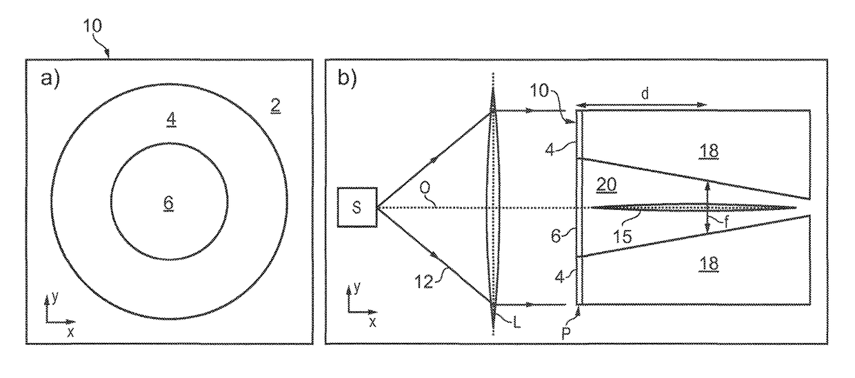
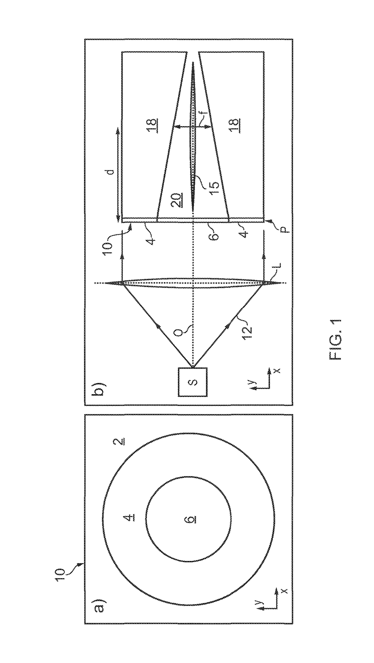
[0048]FIG. 1a is a conceptual sketch in end view of a super-oscillatory lens 10. The super-oscillatory lens 10 can be formed by a planar mask which defines a blocking area 6 which is opaque to an incident light beam surrounded by a structured, super-oscillatory lensing region 4 which carries a pre-defined pattern to modulate light from the incident light beam in amplitude or phase or both. The region outside the mask, referred to as a surrounding area 2, can be either opaque or transparent depending on overall design considerations for the particular application of interest.

[0049]FIG. 1b is a conceptual sketch in side view of the super-oscillatory lens structure 10 of FIG. 1a. A light source S generates light 12 which is output onto a conventional convex lens L which collimates the light beam and directs it to be incident on the super-oscillatory lens 10. The incident light beam 12 is spatially coherent across the area of the super-oscillatory lens device, or at least the structured...


PUM

PropertyMeasurementUnit
aperture diametersaaaaaaaaaa
diameteraaaaaaaaaa

Abstract

A super-oscillatory lens (10) having a pre-defined pattern to spatially modulate the light beam in amplitude and / or phase which has a blocking element (6) formed integrally with the lens, or as a separate component adjacent to the lens, which is opaque to the light beam to cause diffraction of the light beam around the blocking element and formation of a shadow region (20). The lens and blocking element focus the light beam to form an elongate needle-shaped focus (15) in the shadow region (20). In any application in which it is necessary to scan a small spot over a surface, compared with a conventional objective lens focus the elongate shape of the focus relaxes the requirement on a feedback loop to maintain a constant separation between a scan head and a surface being scanned. The elongate shape is also ideal shape for materials processing applications.

Description

[0001]This application is a national phase of International Application No. PCT / GB2013 / 050114 filed Jan. 18, 2013 and published in the English language.BACKGROUND OF THE INVENTION[0002]The invention relates to super-oscillatory lens devices and methods.[0003]The last decade has seen numerous efforts to achieve imaging resolution beyond that of the Abbe-Rayleigh diffraction limit, which proscribes the visualization of features smaller than about half of the wavelength of light with optical instruments. The main direction of research aiming to break this limit seeks to exploit the evanescent components containing fine detail of the electromagnetic field distribution.[0004]Scanning near-field optical microscopy (SNOM) has been well developed since the work of Betzig on optical fibre tips in the early 1990's [1, 2]. Other near-field imaging techniques have also been developed. Near-field imaging techniques exploit evanescent fields so require samples to be positioned very close to a sca...

Claims


Application Information

Patent Timeline
Patent Type & Authority Patents(United States)
IPC IPC(8): G02B26/00G02B27/46G02B27/09G02B27/58G02F1/21G02B27/44G02F1/01
CPCG02F1/21G02B27/0988G02B27/44G02B27/46G02B27/58G02B27/0075
Inventor ZHELUDEV, NIKOLAY IVANOVICHSAVO, SALATOREROY, TAPASHREESAVINOV, VASSILIDENNIS, MARK RICHARDROGERS, EDWARD THOMAS FOSSLINDBERG, JARI JUHANI
Owner UNIV OF SOUTHAMPTON
Why Eureka
Try Eureka