
Microfocus X-ray Source

An X-ray and micro-focus technology, applied in the directions of X-ray tube, X-ray tube electrode, X-ray tube parts, etc., can solve the problem of low heat dissipation efficiency of X-ray source anode, achieve small focus, high power, focusing easy effect

Active Publication Date: 2022-02-01
姚智伟
View PDF4 Cites 0 Cited by
  • Summary
  • Abstract
  • Description
  • Claims
  • Application Information

AI Technical Summary

Problems solved by technology

[0005] Therefore, the technical problem to be solved by the present invention is to overcome the defects caused by the low heat dissipation efficiency of the X-ray source anode in the prior art

Method used


Image

  • Microfocus X-ray Source
  • Microfocus X-ray Source
  • Microfocus X-ray Source

Examples


Embodiment Construction

[0038] The technical solutions of the present invention will be clearly and completely described below in conjunction with the accompanying drawings. Apparently, the described embodiments are some of the embodiments of the present invention, but not all of them. Based on the embodiments of the present invention, all other embodiments obtained by persons of ordinary skill in the art without making creative efforts belong to the protection scope of the present invention.

[0039] In the description of the present invention, it should be noted that the terms "center", "upper", "lower", "left", "right", "vertical", "horizontal", "inner", "outer" etc. The indicated orientation or positional relationship is based on the orientation or positional relationship shown in the drawings, and is only for the convenience of describing the present invention and simplifying the description, rather than indicating or implying that the referred device or element must have a specific orientation, ...


PUM


Abstract

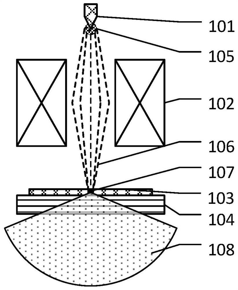
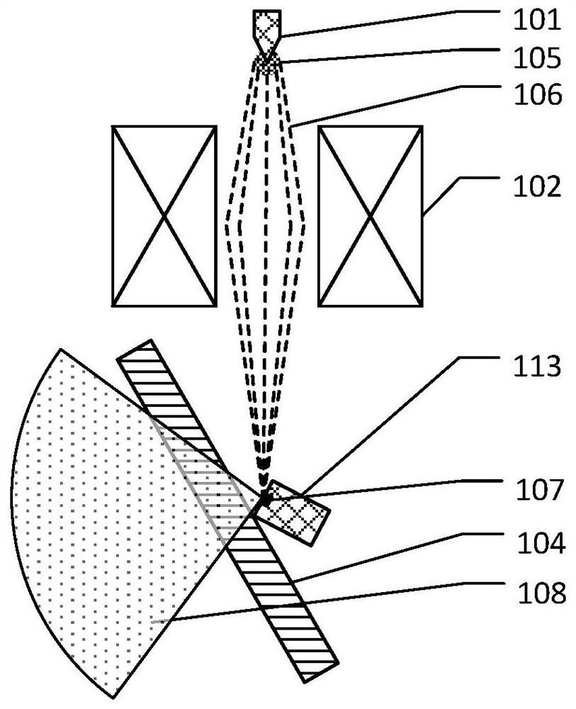
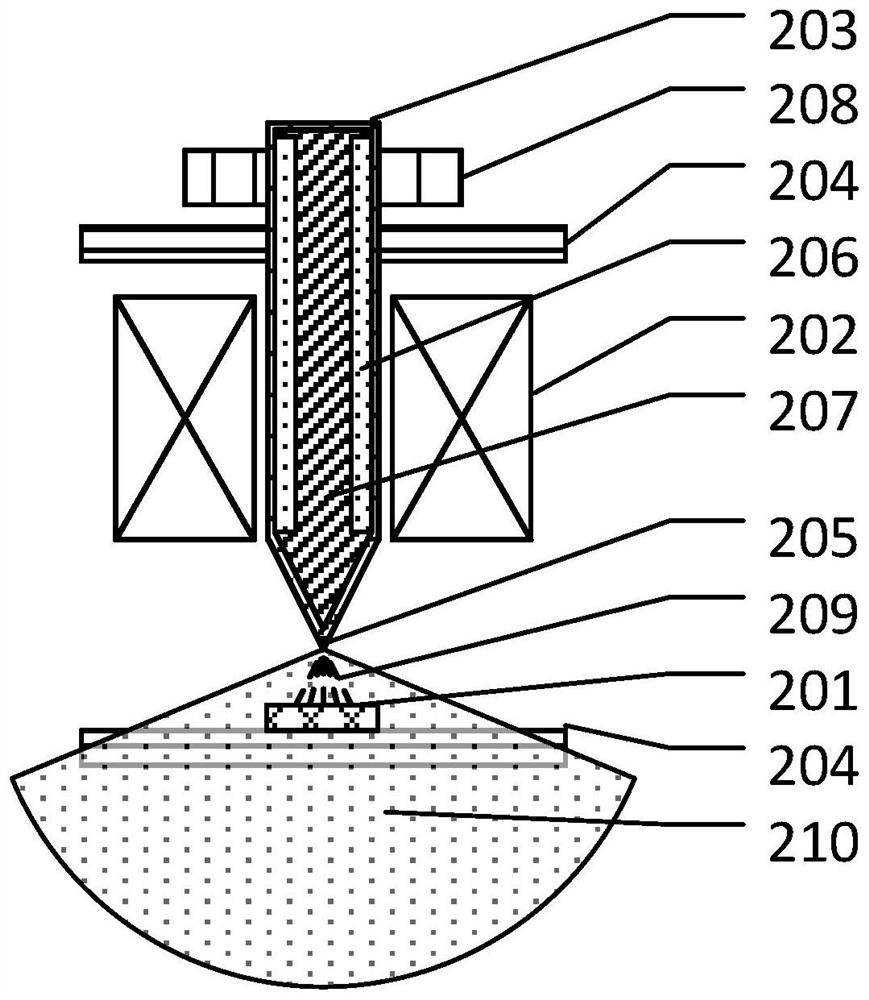
A micro-focus X-ray source, comprising a glass vacuum chamber wall that is columnar as a whole and has a preset distance between the upper and lower layers; the field emission cathode is arranged at the lower glass vacuum chamber wall; the upper part of the field emission cathode is provided with a micro heat pipe The anode, the upper part of the micro heat pipe anode runs through the glass vacuum chamber wall and extends upward; focusing coils are respectively arranged around the part of the micro heat pipe anode located inside the glass vacuum chamber wall. The kinetic energy of field emitted electron beams is distributed over a narrow range and the focal point can be even smaller. The anode using the heat pipe for heat dissipation has greater thermal conductivity and can withstand greater power, and the anode of the heat pipe for heat dissipation uses a cooling fluid inside, and the two-phase characteristic of the cooling fluid further achieves that the cooling fluid is located in the glass vacuum chamber wall to absorb heat, It is located outside the wall of the vacuum chamber for the purpose of heat dissipation, to achieve the uniform temperature state of the anode of the heat pipe heat dissipation.

Description

technical field [0001] The invention relates to the technical fields of micro-focus X-ray imaging, X-ray nondestructive testing, X-ray diffraction, X-ray fluorescence spectroscopy, etc., and specifically relates to a micro-focus X-ray source using heat pipe cooling, magnetic field focusing and field emission cold cathode. Background technique [0002] Field electron emission (field emission) has been studied theoretically for many years as a purely quantum phenomenon. Many kinds of field emission electron sources have been developed, the most representative ones are metal cone cathodes and carbon nanotube cathodes. The X-ray cathode based on field emission technology can be used to develop high-speed pulsed X-ray generating devices because of its low operating temperature and no need for preheating. This is not possible with traditional tungsten hot cathode X-ray sources. [0003] The microfocus X-ray source is specially developed for X-ray non-destructive testing. The ti...

Claims


Application Information

Patent Timeline
Patent Type & Authority Patents(China)
IPC IPC(8): H01J35/10
CPCH01J35/106
Inventor 姚智伟孙泳海
Owner 姚智伟
Learn More