Spectroscopic ellipsometers

a spectroscopic and ellipsometer technology, applied in the field of inspection and measurement systems, can solve problems such as limiting the speed of measuremen

Active Publication Date: 2011-08-16
RAINTREE SCI INSTR SHANGHAI
View PDF4 Cites 1 Cited by
  • Summary
  • Abstract
  • Description
  • Claims
  • Application Information

AI Technical Summary

Benefits of technology

[0016]An advantage of the present invention is that it provides methods and devices for an ellipsometer that can focus on small focus spots.
[0017]Another advantage of this invention is that it provides methods and devices for an ellipsometer that can simultaneously polarize, reflect, analyze, and detect several rays.
[0018]Another advantage of this invention is that it provides methods and devices for an ellipsometer that can simultaneously polarize, reflect, analyze, and detect several rays without any mechanical moving parts.

Problems solved by technology

This limits the speed of the measurement.

Method used


Image

  • Spectroscopic ellipsometers
  • Spectroscopic ellipsometers
  • Spectroscopic ellipsometers

Examples


Embodiment Construction

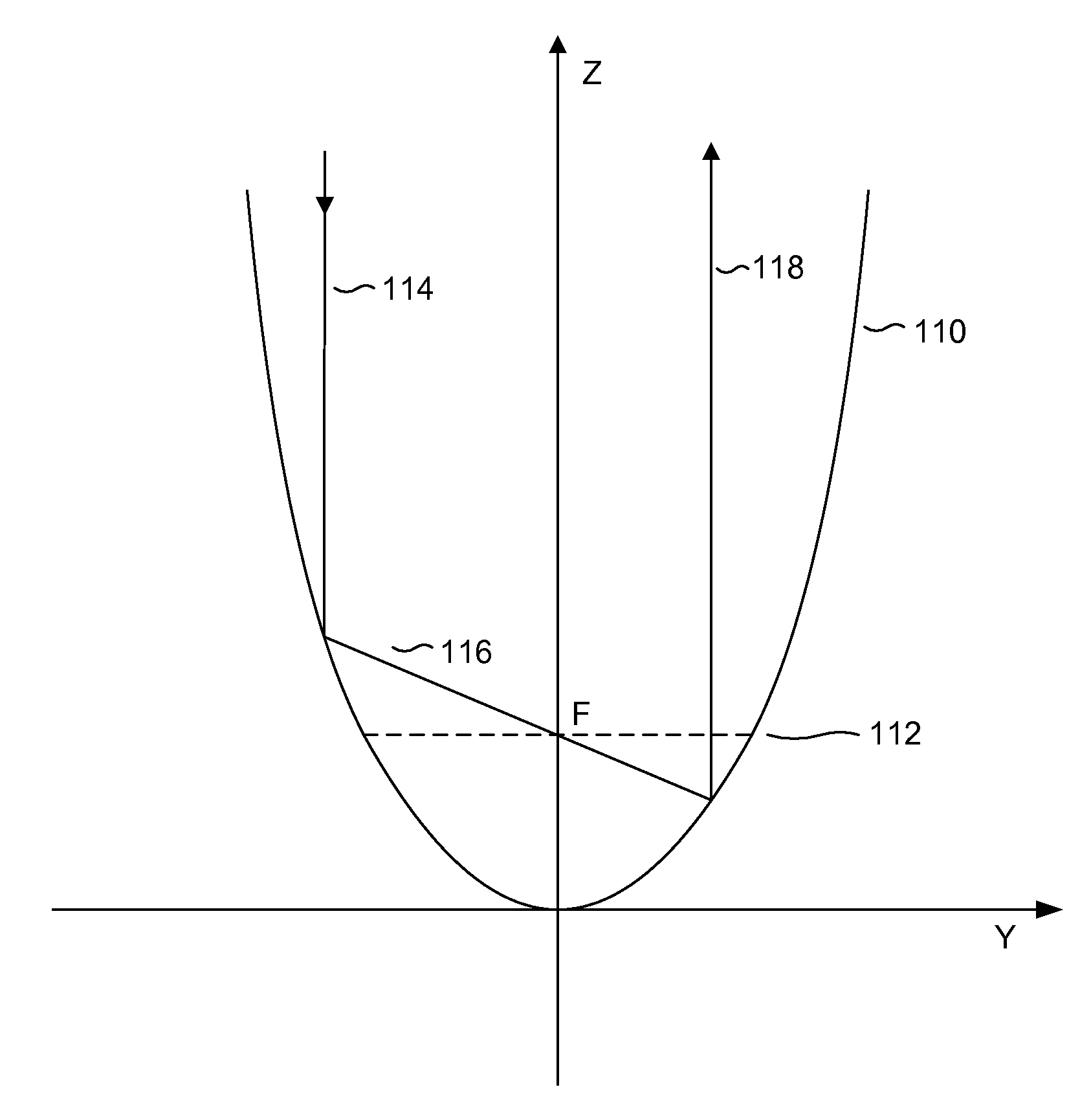
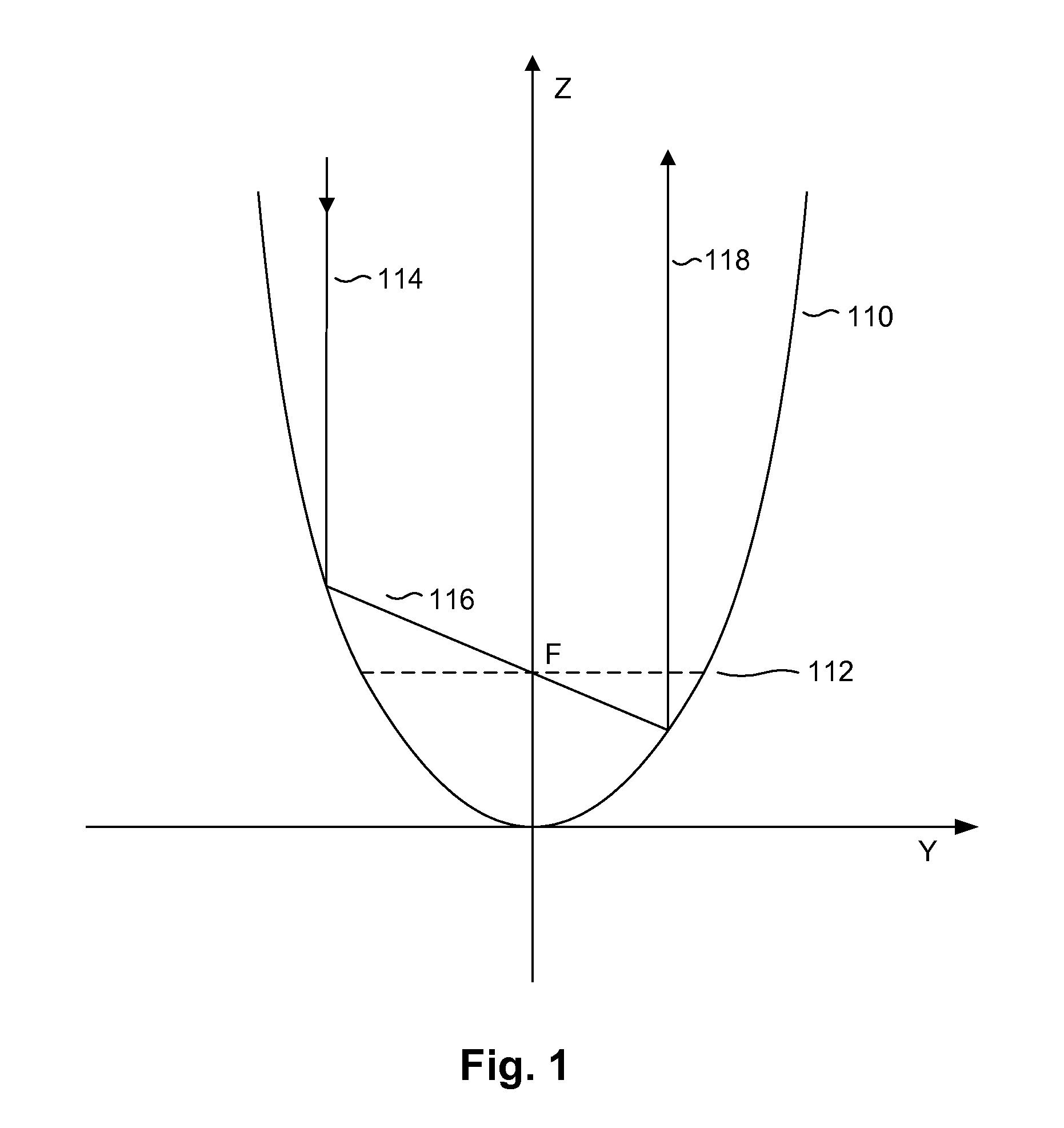
[0028]Referring to FIG. 1, an underlying concept of the embodiments of the present invention is explained. Given a parabola 110 disposed on a y-axis and a z-axis, conceptually, the shape of the parabola can be described be a simple mathematical function, z=ay2, where incoming rays parallel to the z-axis would intersect the z-axis at its focal point “F”, where the focal point is at (0, ¼a), and “a” is a constant. The incoming ray intersects the parabolic surface and it is redirected towards the focal point at the incident plane 112 (the plane that is perpendicular to the axis of symmetry and passes through the focal point, “F”).

[0029]Here, as shown, the incidental incoming light ray 114 is parallel to the axis of symmetry. The ray hits the parabolic surface and the parabolic reflector, by virtue of its properties, directs the beam towards its focal point and intersects the z-axis at intersection point “F”. After the intersection, the ray hits the parabolic surface again, and the para...


PUM


Abstract

The present invention discloses an optical measurement and / or inspection device that, in one application, may be used for inspection of semiconductor devices. A method is disclosed for extracting information of a device-under-test for an ellipsometer, comprising the steps: providing a plurality of incoming polarized beams using a plurality of polarizers, where each of the beams being polarized at a designated polarizing angle; using a parabolic reflector to focus said plurality of incoming polarized beams on a spot on a DUT; using a parabolic reflector to collect a plurality of beams reflected from said DUT; and analyzing said collected beams using a plurality of analyzers, wherein each of the analyzers having a designated polarizing angle with respect to its respective polarizer.

Description

PRIORITY CLAIM[0001]This application claims priority from a provisional patent application entitled “Spectroscopic Ellipsometer Without Moving Parts” filed on Apr. 24, 2006, having an application No. 60 / 793,926. This application further claims priority from a non-provisional patent application entitled “Optical Focusing Devices” filed on Apr. 16, 2007, having an application Ser. No. 11 / 735,979. These applications are incorporated herein by reference in its entirety.FIELD OF INVENTION[0002]The present invention relates to the inspection and measurement systems, and in particular, to optical inspection and measurement of devices under test such as semiconductor devices and / or wafers.BACKGROUND[0003]Spectroscopic ellipsometry is a very power optical measurement technology widely used in semiconductor manufacturing, optical coating and material analysis. The ellipsometer measures the complex ratio of reflectivity of Rp and Rs, where Rp is the reflectivity of the electrical field whose d...

Claims


Application Information

Patent Timeline
Patent Type & Authority Patents(United States)
IPC IPC(8): G01B11/30
CPCG01B11/0625G01N21/211G01N21/9501G01N2021/213G01N2021/8427G01N2201/0636G01N2201/0637
Inventor LU, TONGXINWANG, XIAOHAN
Owner RAINTREE SCI INSTR SHANGHAI
Why Eureka
Try Eureka