Directionally controlled elastically deployable roll-out solar array

a solar array and elastic technology, applied in the field of solar arrays, can solve the problems of increasing weight and complexity, adding undesired parts, and limiting the use of flexible-blanket solar arrays, and achieve the effect of preventing shear displacemen

Active Publication Date: 2017-04-04
DEPLOYABLE SPACE SYST
View PDF30 Cites 12 Cited by
  • Summary
  • Abstract
  • Description
  • Claims
  • Application Information

AI Technical Summary

Benefits of technology

[0014]The present disclosure provides an elastic roll out boom including a thin wall, tubular, elongate structure having a plurality of interlocking elements disposed in spaced-apart relation along the surface thereof. The elastic roll out boom is configured to be flattened and rolled tightly to form a roll in a stowed configuration. The plurality of interlocking elements are positioned such that a first interlocking element engages a second interlocking element when the elastic roll out boom is in the stowed configuration. This prevents shear displacement between layers of the roll out boom.

Problems solved by technology

Flexible-blanket solar arrays have been typically been limited to crystalline solar cell arrays packaged in a long roll or pleated stack that is deployed using a separate deployment boom or hub structure requiring external motor power for deployment motive force.
These flexible array deployment structures have typically consisted of very complex mechanical systems such as coilable or articulated truss booms, or radially oriented spars that rotate about a central hub, which can add undesired parts, complexity, weight and cost to implement.
Historical solutions used to increase deployment force margin in a linearly deploying boom have been to increase the size and capability of structural components and use deployment actuators (such as springs or motors) to “force” the boom out, further increasing weight and complexity.
Utilizing the elastic strain energy inherent in the deployment boom material alone to achieve high deployment force has not been successfully used in the prior art for deployable boom-type solar array structures.
This is because in order to raise the available actuation energy to levels sufficient to achieve acceptable deployment force margin, typical metallic or fiber-composite materials are too highly stressed (they are unacceptably close to failure), and the kinematics of deployment are difficult to control and predict due to the high internal energy and ungoverned nature of the stowed assembly upon release.
As the size of the solar cell deployed area and the solar array supporting structure increase, the stiffness of the solar cell array decreases and, as a result, the vibration frequency decreases and disturbance deflections increase.
The ability of the spacecraft attitude control system to orient the spacecraft may be impaired if the deflections due to low-frequency solar array movement are excessive.
These prior efforts have resulted in solar array designs tending to involve difficult and time consuming manufacturing, higher complexity and higher cost.
The current larger market for spacecraft is demanding significant decreases in the cost of all spacecraft systems and payloads, including solar arrays.
This, in turn, effects unidirectional boom deployment.
The containment strap controls the rate of diameter reduction of the stowed roll during deployment which, in turn, effects unidirectional boom deployment.

Method used


Image

  • Directionally controlled elastically deployable roll-out solar array
  • Directionally controlled elastically deployable roll-out solar array
  • Directionally controlled elastically deployable roll-out solar array

Examples


Embodiment Construction

Glossary of Terms

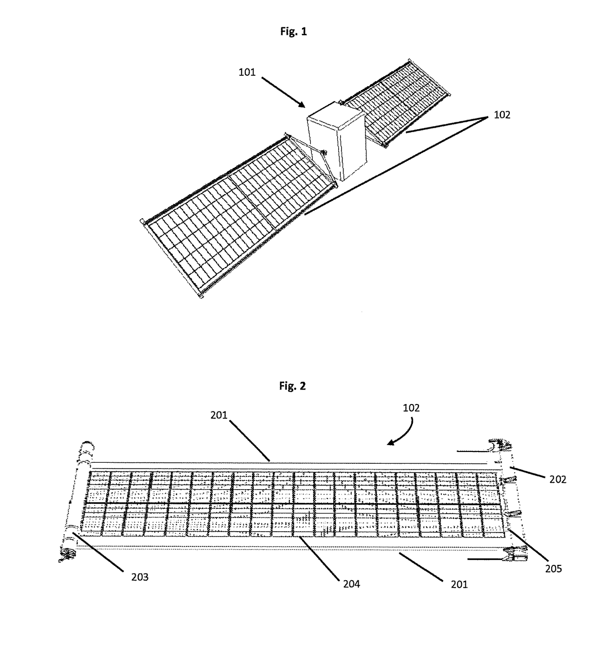
[0057]Solar Array—A structure that is stowable in a small volume for shipment and launch, and that is deployable when in space to expose a large surface area of photovoltaic collectors (solar cells) to the sun, and that is mechanically and electrically attached to a spacecraft vehicle to provide power for spacecraft operations.

[0058]Flexible solar array—A solar array that includes a rollable or foldable thin flexible blanket or substrate to which the solar cells are mounted.

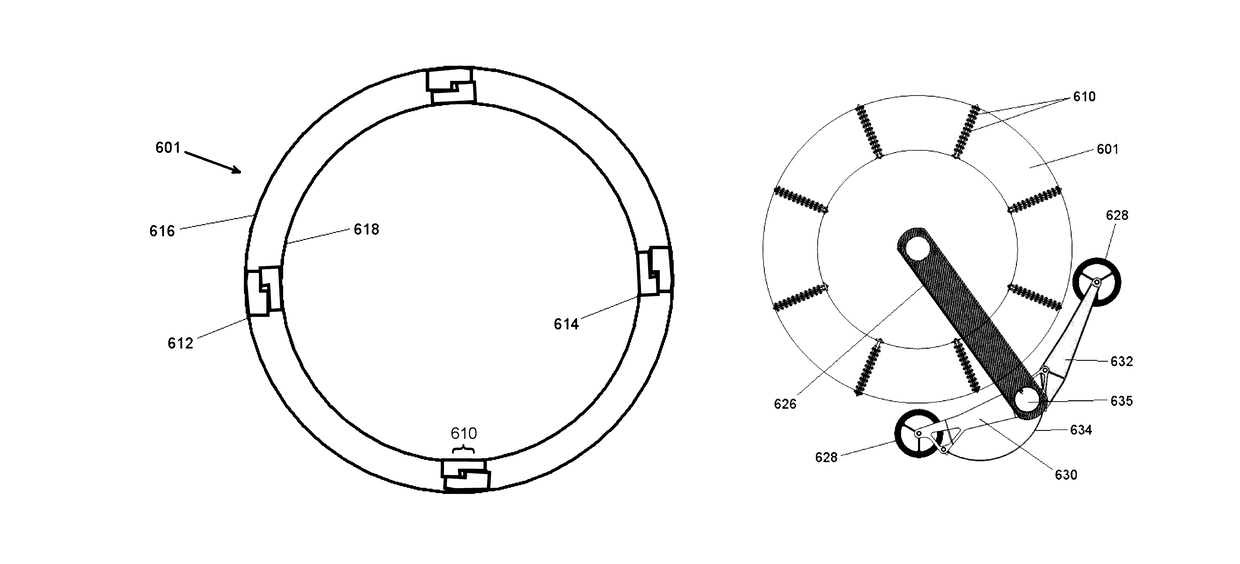
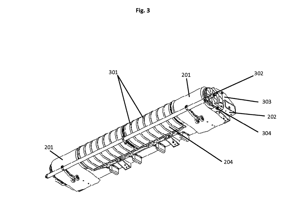
[0059]Rollout boom—A thin-walled metallic or composite reinforced slit-tube (open section) or closed section hollow structural member. One or more booms can be used as the primary longitudinal deployment and deployed structural member of the solar array. The thin-walled elastic nature of the booms allow them to be flattened and rolled up into an extremely compact stowage volume.

[0060]Elastic roll out boom—A roll out boom that that is constructed such that it is self-deploying elastically though i...


PUM


Abstract

An elastic roll out boom includes a thin wall, tubular, elongate structure having a plurality of interlocking elements disposed in spaced-apart relation along the surface thereof. The elastic roll out boom is configured to be flattened and rolled tightly to form a roll in a stowed configuration. The plurality of interlocking elements are positioned such that a first interlocking element engages a second interlocking element when the elastic roll out boom is in the stowed configuration. This prevents shear displacement between layers of the roll out boom.

Description

RELATED APPLICATIONS[0001]This application is a continuation-in-part of U.S. patent application Ser. No. 14 / 173,252, entitled “Directionally Controlled Elastically Deployable Roll-Out Solar Array” and filed Feb. 5, 2014, which application was in turn a continuation of U.S. patent application Ser. No. 13 / 010,739, entitled “Directionally Controlled Elastically Deployable Roll-Out Solar Array” and filed Jan. 20, 2011. This application claims priority to the aforementioned applications and incorporated them both herein by reference.STATEMENT REGARDING FEDERALLY SPONSORED RESEARCH OR DEVELOPMENT[0002]The U.S. Government may have certain rights in this invention pursuant to Contract No. FA9453-08-M-0094.BACKGROUND AND FIELD[0003]1. Field[0004]The present disclosure relates generally to the field of solar arrays for space-based applications and, more specifically, to flexible-blanket solar arrays deployable from a spacecraft that are stowable in a small volume for shipment and launch.[0005...

Claims


Application Information

Patent Timeline
Patent Type & Authority Patents(United States)
IPC IPC(8): B64G1/44B64G1/22
CPCB64G1/443B64G1/222Y10T428/1362
Inventor SPENCE, BRIAN R.WHITE, STEPHEN F.
Owner DEPLOYABLE SPACE SYST
Why Eureka
Try Eureka