Apparatus for controlling autonomously navigating utility vehicle

a technology for utility vehicles and autonomous navigation, applied in vehicle position/course/altitude control, process and machine control, instruments, etc., can solve the problems of unavoidable proportional increase in cost and troublesome perfect calibration of such characteristics, and achieve accurate and easy calibration of angular velocity sensors. , the effect of low cos

Active Publication Date: 2017-04-04
HONDA MOTOR CO LTD
View PDF6 Cites 3 Cited by
  • Summary
  • Abstract
  • Description
  • Claims
  • Application Information

AI Technical Summary

Benefits of technology

[0008]Therefore, the object of this invention is to overcome the aforesaid problem by providing an apparatus for controlling an autonomously navigating utility vehicle enabling calibration of an angular velocity sensor accurately and easily at low cost without incorporating another sensor like the direction sensor.

Problems solved by technology

Moreover, perfect calibration of such characteristics is very troublesome because characteristic variance differs from one sensor to another.
However, when a high-precision sensor is added for angular velocity sensor calibration as in the teaching of Patent Document 1, a proportional increase in cost is unavoidable.

Method used


Image

  • Apparatus for controlling autonomously navigating utility vehicle
  • Apparatus for controlling autonomously navigating utility vehicle
  • Apparatus for controlling autonomously navigating utility vehicle

Examples


Embodiment Construction

[0020]An apparatus for controlling an autonomously navigating utility vehicle according to an embodiment of this invention is explained with reference to the attached drawings in the following.

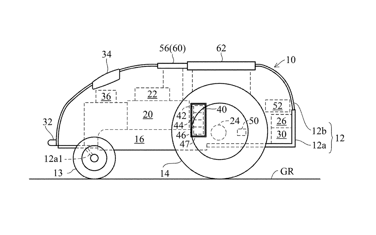
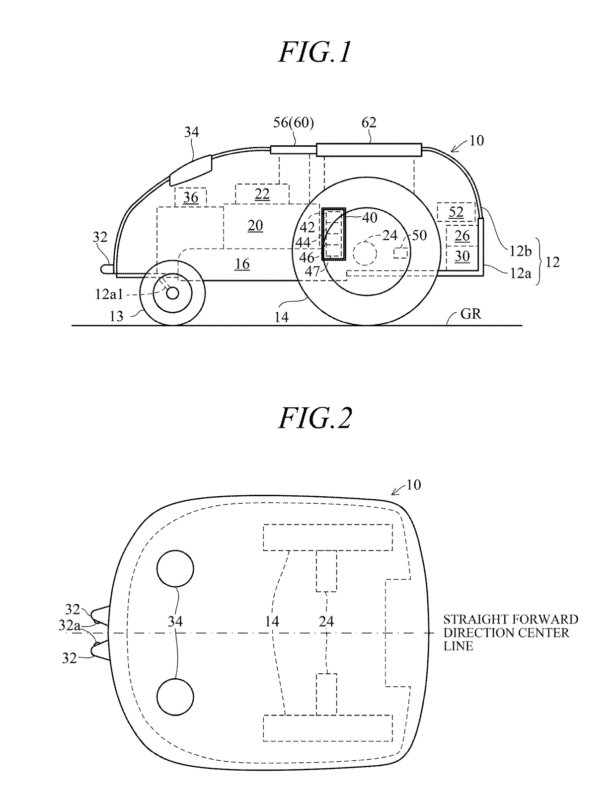
[0021]FIG. 1 is an overall conceptual diagram of the apparatus for controlling an autonomously navigating utility vehicle according to the embodiment, and FIG. 2 is a plan view of the autonomously navigating utility vehicle shown in FIG. 1.

[0022]As shown in FIGS. 1 and 2, reference symbol 10 designates an autonomously navigating utility vehicle, e.g., a mower; hereinafter called “utility vehicle”. A body 12 of the utility vehicle 10 comprises a chassis 12a and a frame 12b attached thereto. The utility vehicle 10 is equipped with relatively small diameter left and right front wheels 13 rotatably fastened to a front end of the chassis 12a through stays 12a1 and relatively large diameter left and right rear wheels 14 rotatably fastened to the chassis 12a directly.

[0023]A work unit, e.g., a mower ...


PUM


Abstract

In an autonomously navigating utility vehicle adapted to run a working area defined by a laid boundary wire autonomously having a pair of magnetic sensors installed on either sides of the vehicle at positions laterally symmetrical with respect to a vehicle straight forward center line to produce outputs indicating intensity of magnetic field of the wire, an angular velocity sensor adapted to produce an output indicating angular velocity around a vertical axis of the vehicle, the vehicle is controlled to move to a prescribed position at which an angle of the center line relative to the laid wire becomes a reference angle based on the outputs of the magnetic sensors, and to turn by 180 degrees, and calibrates the output of the angular velocity sensor by outputs of the angular velocity sensor obtained at the turning.

Description

CROSS-REFERENCE TO RELATED APPLICATION[0001]This application is based upon and claims the benefit of priority from Japanese Patent Application No. 2014-172443 filed on Aug. 27, 2014, the contents of which are incorporated herein by reference.BACKGROUND OF THE INVENTIONField of the Invention[0002]This invention relates to an apparatus for controlling an autonomously navigating utility vehicle that navigates autonomously in a working area, particularly to a controlling apparatus that calibrates an output of an angular velocity sensor (yaw-rate sensor, gyroscopic device) installed in the utility vehicle.Description of Related Art[0003]Various prior art techniques have been reported for calibrating an output of an angular velocity sensor that produces the output indicating angular velocity (yaw rate) around a center-of-gravity z-axis (vertical axis) of an autonomously navigating utility vehicle, whose time-integrating value indicates a turn angle (yaw angle) around the axis. As an examp...

Claims


Application Information

Patent Timeline
Patent Type & Authority Patents(United States)
IPC IPC(8): G05D1/00G01P21/00G01D5/20G05D1/02
CPCG05D1/0088G01D5/2006G01P21/00G05D1/027G05D1/0265G05D1/0274G05D2201/0208
Inventor NAKAYAMA, KEIICHIMATSUI, YUKIYAMAMURA, MAKOTO
Owner HONDA MOTOR CO LTD
Why Eureka
Try Eureka