Method and system for efficient modeling of specular reflection

a specular reflection and efficient technology, applied in the field of computer generated graphics, can solve the problems of less realistic images to speed up the rendering, inconvenient designers, and a relatively resource-intensive process for three-dimensional rendering, and achieve the effect of sufficient realism, fast and realistic simulation

Active Publication Date: 2017-04-11
ARMSTRONG WORLD INDUSTRIES
View PDF91 Cites 4 Cited by
  • Summary
  • Abstract
  • Description
  • Claims
  • Application Information

AI Technical Summary

Benefits of technology

[0016]Implementations of the present invention overcome one or more of the foregoing or other problems in the art with systems, methods, and apparatus configured to allow efficient rendering of realistic specular reflection of objects in a design software application. In particular, one or more implementations of the present invention allow for simulation of specular reflection without having to perform a separate calculation for each light in an environment with multiple lights. In addition, one or more implementations of the present invention have the ability to model specular reflection with sufficient realism while turning off lighting in one area of the scene, and while turning on lighting in another area. In general, one or more implementations of the invention provide fast and realistic simulation of specular reflection, allowing real-time rendering of videos and dynamic scenes in applications such as virtual walk-throughs of interior design spaces, video games, and other virtual environments.

Problems solved by technology

While three-dimensional rendering is becoming a more common feature in CAD programs, three-dimensional rendering is a fairly resource intensive process.
This may be particularly inconvenient to a designer who has to wait for the scene to render after making a change to the layout of the scene.
Alternatively, some rendering programs may use methods of rendering that result in less realistic images to speed up the rendering and use fewer resources.
Because the number of lights is typically large in certain settings, such as in offices and department stores, rendering can slow down (many-fold) in these applications.
A second limitation with conventional methods lies in the algorithm used to calculate specular reflection.
The calculation of the reflection vector R adds to the computational burden for the simulation of specular reflection.
An additional problem exists in conventional methods using the foregoing algorithm.
These methods can substantially increase the computational load and slow down simulation of the object in dynamic scenes.
The foregoing problems make many of the conventional methods too slow to be practical in real-time rendering of dynamic scenes, such as in a virtual walk-through of a three-dimensional architectural model, video games, or other virtual environments.
The convention software then applies the same reflection of the object to different frames of a video for a dynamic scene, regardless of the changes of the incident vector L, reflection vector R, or the viewing vector V. Although this method is computationally simpler than conventional methods that calculate specular reflection for each frame, the realism of a rendered object is substantially inferior when object placement and the viewing angle deviate from the original setting.
The results, however, are not realistic due to the use of a single, global ambient light source, and conventional design spaces tend to incorporate a plurality of light sources.
In addition, ambient occlusion techniques typically do not allow for dynamic differential of lighting in different areas of the layout or scene, due to the single, global light source nature.
Ambient occlusion techniques usually have no ability (or are significantly limited) to turn off lighting in one area of the scene, and turn on lighting in another area.

Method used


Image

  • Method and system for efficient modeling of specular reflection
  • Method and system for efficient modeling of specular reflection
  • Method and system for efficient modeling of specular reflection

Examples


Embodiment Construction

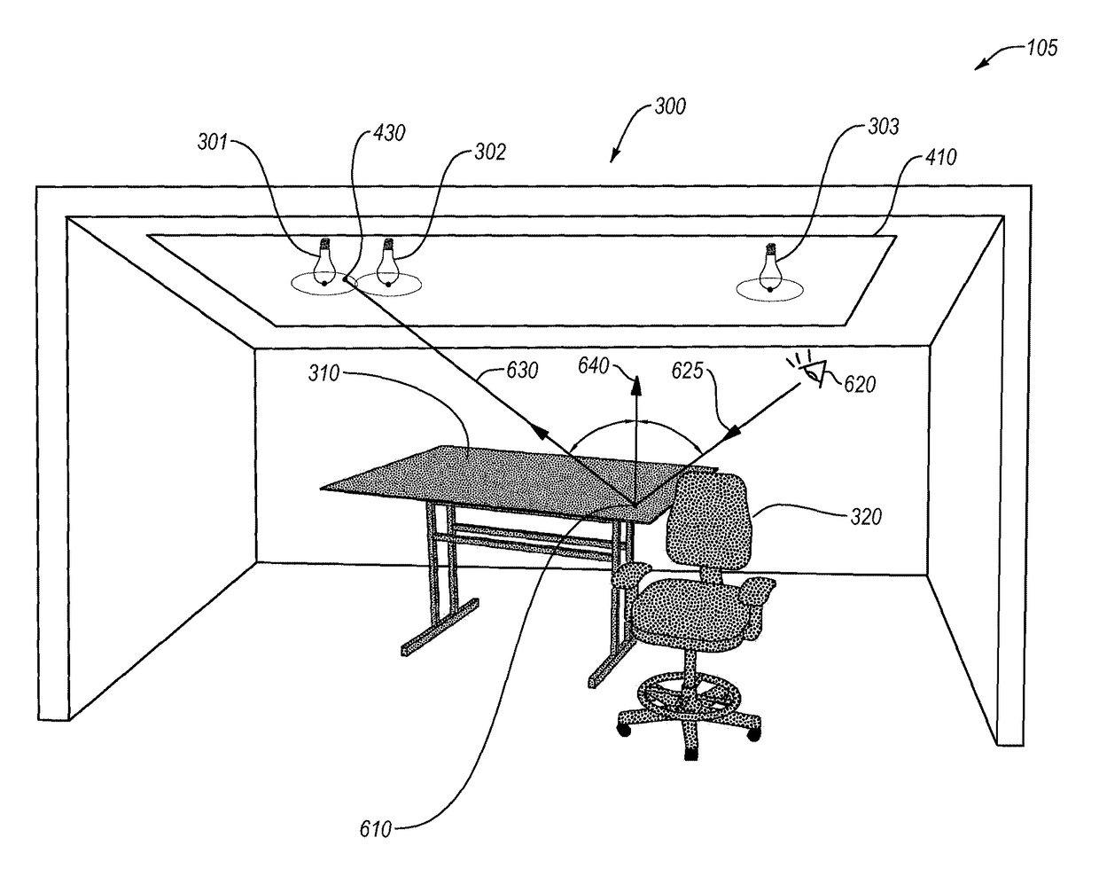
[0031]Implementations of the present invention extend to systems, methods, and apparatus configured to allow efficient rendering of realistic specular reflection of objects in a design software application. In particular, one or more implementations of the present invention allow for simulation of specular reflection without having to perform a separate calculation for each light in an environment with multiple lights. In addition, one or more implementations of the present invention have the ability to model specular reflection with sufficient realism while turning off lighting in one area of the scene, and while turning on lighting in another area. In general, one or more implementations of the invention provide fast and realistic simulation of specular reflection, allowing real-time rendering of videos and dynamic scenes in applications such as virtual walk-throughs of interior design spaces, video games, and other virtual environments.

[0032]For example, one or more implementatio...


PUM


Abstract

Systems, methods, and apparatus allow for the real-time rendering of specular effects within a three-dimensional model. At least one implementation allows a user to create a map that comprises a representation of at least one light source within a three-dimensional model. Furthermore, at least one implementation casts a viewpoint ray to an object surface point, wherein the viewpoint ray comprises a ray extending from a user perspective within the three-dimensional model. Additionally, at least one implementation casts a reflection ray of the viewpoint ray. Further, at least one implementation identifies an intersection point between the reflection ray and the map. Still further, at least one implementation calculates the specular reflection of the object surface point based on the intersection point.

Description

CROSS-REFERENCE TO RELATED APPLICATIONS[0001]The present invention is a 35 U.S.C. §371 U.S. National Stage of PCT Application No. PCT / US2013 / 024009 filed Jan. 31, 2013, entitled “Method and System for Efficient Modeling of Specular Reflection,” the entire content of which is incorporated by reference herein.BACKGROUND OF THE INVENTION[0002]1. The Field of the Invention[0003]The present invention relates generally to computer-generated graphics, and more specifically relates to modeling and rendering specular reflection of light.[0004]2. Background and Relevant Art[0005]As computerized systems have increased in popularity so have the range of applications that incorporate computational technology. Computational technology now extends across a broad range of applications, including a wide range of productivity and entertainment software. Indeed, computational technology and related software can now be found in a wide range of generic applications that are suited for many environments,...

Claims


Application Information

Patent Timeline
Patent Type & Authority Patents(United States)
IPC IPC(8): G06T15/06G06T15/50G06T15/80
CPCG06T15/06G06T15/50G06T15/80G06T2215/12
Inventor HOWELL, JOSEPH S.
Owner ARMSTRONG WORLD INDUSTRIES
Why Eureka
Try Eureka