Interlock device of ring main unit

Active Publication Date: 2017-04-11
LSIS CO LTD
View PDF16 Cites 2 Cited by
  • Summary
  • Abstract
  • Description
  • Claims
  • Application Information

AI Technical Summary

Benefits of technology

[0022]According to an interlock device of a ring main unit in accordance with an embodiment of the present disclosure, a fuse cover may be closed only when a cable co

Problems solved by technology

In this case, the relevant circuit will be in an always-on state, and thus there is a risk of accident such as dielectr

Method used


Image

  • Interlock device of ring main unit
  • Interlock device of ring main unit
  • Interlock device of ring main unit

Examples


Embodiment Construction

[0036]Hereinafter, a preferred embodiment of the present invention will be described in detail with reference to the accompanying drawings to such an extent that the present invention can be easily implemented by a person having ordinary skill in the art to which the present invention pertains, but it does not mean that the technical concept and scope of the present invention are limited due to this.

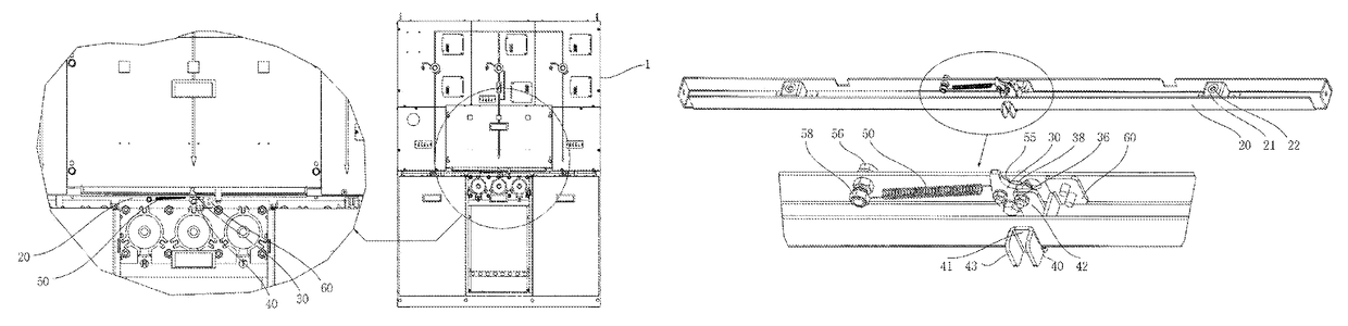
[0037]FIG. 3 is a perspective view illustrating an interlock device state when the fuse cover and cable cover are mounted in a ring main unit according to an embodiment of the present disclosure, and FIG. 4 is a perspective view illustrating an interlock device state when only the fuse cover is mounted and the cable cover is removed, and FIG. 5 is a perspective view of an interlock device in a ring main unit according to an embodiment of the present disclosure, and FIG. 6 is an exploded perspective view illustrating constituent elements excluding an interlock frame in FIG. 5, and FIG. 8 ...


PUM


Abstract

The present invention relates to an interlock device of a ring main unit, and more particularly, to an interlock device of a ring main unit in which a fuse cover can be closed in interlock with a cable cover.
An interlock device of a ring main unit according to an embodiment of the present disclosure may include an interlock frame provided in part of the ring main unit, a cam on part of which an engaging portion is protruded and formed and on the other part of which a slit is formed, rotatably provided within the interlock frame, an operating plate an end of which is coupled to the slit to perform a vertical movement, and a spring an end of which is fixed to part of the cam to store an elastic force due to the movement of the cam.

Description

CROSS-REFERENCE TO RELATED APPLICATIONS[0001]Pursuant to 35 U.S.C. §119(a), this application claims the benefit of earlier filing date and right of priority to Korean Patent Application No. 10-2015-0010786, filed on Jan. 22, 2015, the contents of which are hereby incorporated by reference herein in its entirety.BACKGROUND OF THE INVENTION[0002]1. Field of the Invention[0003]The present invention relates to an interlock device of a ring main unit, and more particularly, to an interlock device of a ring main unit in which a fuse cover can be closed in interlock with a cable cover.[0004]2. Description of the Related Art[0005]In general, as a device used to monitor, control and protect an electrical system configured to transmit and distribute power sent to customers through transmission and distribution, ring main unit (RMU) may be configured with an assembly of a circuit breaker, a switchgear, grounds and conductors within a structure that is sealed and insulated by SF6 gas.[0006]A ri...

Claims


Application Information

Patent Timeline
IPC IPC(8): H01H9/20H01H71/02H01H9/04H01H31/06H01H9/22H02B7/01H01H85/25H02B11/26
CPCH01H9/20H01H9/04H01H31/06H01H71/02H01H9/22H01H85/25H02B7/01H02B11/26H01H2300/024H01H9/226H01H33/48H01H33/662
Inventor LEE, DONG SIK
Owner LSIS CO LTD
Why Eureka
Try Eureka