Control apparatus of an AC generator for a vehicle

a control apparatus and ac generator technology, applied in the direction of electric generator control, electric generator control, dynamo-electric converter control, etc., can solve the problems of the control voltage, and achieve the effect of increasing the continuity rate of electric power supply, increasing the regeneration energy, and increasing the size of the generator

Active Publication Date: 2017-04-11
MITSUBISHI ELECTRIC CORP
View PDF45 Cites 0 Cited by
  • Summary
  • Abstract
  • Description
  • Claims
  • Application Information

AI Technical Summary

Benefits of technology

[0009]A control apparatus of an AC generator for a vehicle according to the present invention, in which an AC output current is rectified and supplied to a vehicle mounted battery and an electric load of the vehicle, is provided with a regulator that controls an output voltage of the generator by controlling a continuity rate of electric power supply to a field coil of the generator, wherein the regulator suppresses the continuity rate of electric power supply to the field coil at the time of steady operation of the vehicle, and switches a suppression value of the continuity rate of electric power supply so as to increase the continuity rate of electric power supply at the time of deceleration operation of the vehicle.
[0010]According to the present invention, by constructing the control apparatus in such a manner that an overpower electric current can be obtained by a short-time rated operation of the generator, it is possible to obtain still larger regeneration energy, without increasing the size of the generator.

Problems solved by technology

The conventional control apparatus of an AC generator for a vehicle can change the control voltage by means of external control, and an amount of rise in the output current of the generator can be expected corresponding to an amount of rise in the control voltage, but the amount of rise in the control voltage is limited to within the rated range of the generator, and hence there has been a problem that it is necessary to make the size of the generator larger in order to obtain a much higher output voltage.

Method used


Image

  • Control apparatus of an AC generator for a vehicle
  • Control apparatus of an AC generator for a vehicle
  • Control apparatus of an AC generator for a vehicle

Examples


first embodiment

[0018

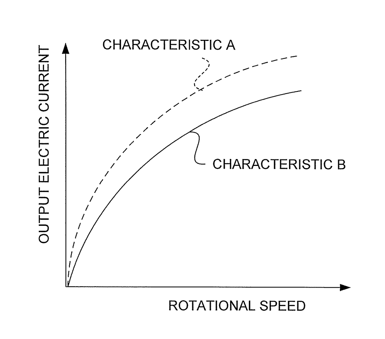
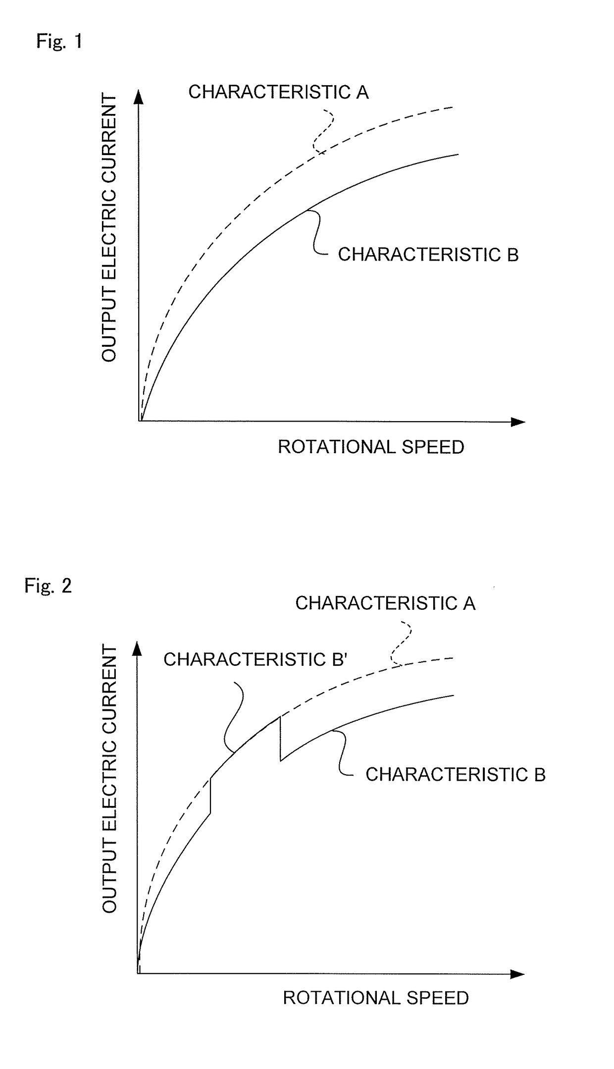
[0019]FIG. 1 is an explanatory view schematically showing one example of an output electric current characteristic of a generator to which a first embodiment of the present invention is to be applied. In addition, FIG. 2 is an explanatory view schematically showing one example of an output electric current characteristic of the generator in cases where the first embodiment of the present invention has been applied to the generator.

[0020]In FIG. 1 and FIG. 2, the axis of abscissa represents the rotational speed of the generator, and the axis of ordinate represents the output current of the generator, wherein a characteristic A indicated by a broken line shows the output current characteristic of the generator at the time of a short-time rated operation thereof when a field coil of the generator is overexcited (an electrical energization of 100%).

[0021]In FIG. 1, a characteristic B indicated by a solid line is the output current characteristic of the generator at the time of a co...

second embodiment

[0049

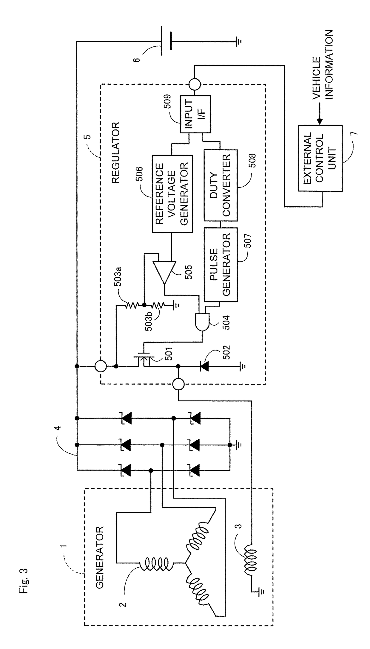
[0050]Here, note that in the above-mentioned first embodiment (FIG. 3), provision has been made for the external control unit 7 that generates not only a control voltage command for switching the control voltage, but also a continuity rate switching command for switching the continuity rate of electric power supply to the field coil 3 and supplies them to the regulator 5, but instead, as shown in FIG. 4, for example, a conventional external control unit 7A may be provided which generates only a control voltage command, and a detection signal from a rotational change detection part 510 may be used as the continuity rate switching command to the duty conversion part (the duty converter 508).

[0051]FIG. 4 is a circuit block diagram showing a control apparatus of an AC generator for a vehicle according to a second embodiment of the present invention, wherein those components which are similar to the above-mentioned ones (refer to FIG. 3) are denoted by the same reference numerals an...

third embodiment

[0059

[0060]Here, note that in the above-mentioned second embodiment (FIG. 4), the rotational change detection part 510 is used for generating a continuity rate switching command to the duty conversion part (the duty converter 508), but a control voltage rise detection part 511 may be used in place of the rotational change detection part 510, as shown in FIG. 5.

[0061]FIG. 5 is a circuit block diagram showing a control apparatus of an AC generator for a vehicle according to a third embodiment of the present invention, wherein those components which are similar to the above-mentioned ones (refer to FIG. 4) are denoted by the same reference numerals and characters as those in the above-mentioned embodiments, or with “B” being attached to reference numerals, and a detailed description thereof is omitted.

[0062]In FIG. 5, the regulator 5B is provided with the control voltage rise detection part 511 that is inserted between an output terminal of an input interface 509A and an input terminal...


PUM


Abstract

A control apparatus of an AC generator for a vehicle can obtain large regeneration energy without making the size of the generator large. In the control apparatus in which an AC output current is rectified and supplied to a vehicle mounted battery (6) and an electric load of the vehicle, provision is made for a regulator (5) that controls a continuity rate of electric power supply to a field coil (3) of a generator (1) by controlling an output voltage of the generator (1). The regulator (5) suppresses the continuity rate of electric power supply to the field coil (3) at the time of steady operation of the vehicle, and switches a suppression value of the continuity rate of electric power supply so as to increase the continuity rate of electric power supply at the time of deceleration operation of the vehicle.

Description

BACKGROUND OF THE INVENTION[0001]Field of the Invention[0002]The present invention relates to a control apparatus of an AC generator for a vehicle (hereinafter also referred to simply as a “generator”) which serves to accumulate or store regeneration energy of the vehicle in a vehicle mounted battery as generated output or electric power.[0003]Description of the Related Art[0004]In the past, there has been proposed a control apparatus of an AC generator for a vehicle which changes a control voltage (a target value of an output voltage of the generator) by means of external control (for example, see a first patent document as listed below).[0005]In the conventional apparatus described in the above-mentioned first patent document, it becomes possible to expect a rise in an output current of the generator corresponding to a rise in the control voltage.PRIOR ART REFERENCESPatent Documents[0006]First Patent Document: Japanese patent No. 3,102,981SUMMARY OF THE INVENTION[0007]The conventi...

Claims


Application Information

Patent Timeline
Patent Type & Authority Patents(United States)
IPC IPC(8): H02P9/10H02P9/48H02P9/30H02P9/14B60L3/00B60L11/14B60L7/14B60L3/04H02P11/00B60L50/16H02P101/45
CPCH02P9/30B60L3/0061B60L3/04B60L7/14B60L11/14H02P9/48B60L2210/30B60L2210/40B60L2240/421B60L2240/425B60L2250/26H02P2101/45Y02T10/642Y02T10/70Y02T10/7077Y02T10/7241B60L50/16Y02T10/64Y02T10/7072Y02T10/72
Inventor KOMURASAKI, KEIICHISUMIMOTO, KATSUYUKISASAKI, JYUNYATANAKA, KAZUNORI
Owner MITSUBISHI ELECTRIC CORP
Why Eureka
Try Eureka