Aircraft fuel tank ullage gas management system

a fuel tank and management system technology, applied in the direction of electrolysis components, separation processes, chemistry apparatuses and processes, etc., can solve the problems of reducing the available engine power, increasing the aircraft payload, and not having sufficient compressed air

Active Publication Date: 2017-04-18
HAMILTON SUNDSTRAND CORP
View PDF10 Cites 20 Cited by
  • Summary
  • Abstract
  • Description
  • Claims
  • Application Information

AI Technical Summary

Problems solved by technology

Bleed air from an aircraft engine or from an onboard auxiliary power unit can provide a source of compressed air; however, this can reduce available engine power and also must compete with other onboard demands for compressed air, such as the onboard air environmental conditioning system.
Moreover, certain flight conditions such as during aircraft descent can lead to an increased demand for NEA at precisely the time when engines are throttled back so that sufficient compressed air may not be available.
A separate compressor or compressors can be used to provide pressurized air to the membrane gas separator, but this undesirably increases aircraft payload, and also represents another onboard device with moving parts that are subject to maintenance issues or device failure.
Additionally, the membranes in such gas separators are subject to fouling over time.

Method used


Image

  • Aircraft fuel tank ullage gas management system
  • Aircraft fuel tank ullage gas management system
  • Aircraft fuel tank ullage gas management system

Examples


Embodiment Construction

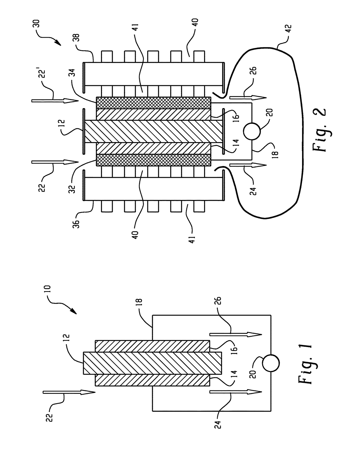
[0010]Referring to FIG. 1, a membrane electrode assembly (MEA) 10 is schematically depicted. The MEA 10 comprises a proton exchange membrane (PEM) 12 having a cathode 14 disposed on one side and an anode 16 disposed on the other side. Exemplary materials from which the MEA 10 can be fabricated include proton-conducting ionomers and ion-exchange resins. Ion-exchange resins useful as proton conducting materials include hydrocarbon- and fluorocarbon-type resins. Fluorocarbon-type resins typically exhibit excellent resistance to oxidation by halogen, strong acids, and bases. One family of fluorocarbon-type resins having sulfonic acid group functionality is NAFION™ resins (commercially available from E.I. du Pont de Nemours and Company, Wilmington, Del.). Alternatively, instead of an ion-exchange membrane, the separator 12 can be comprised of a liquid electrolyte, such as sulfuric or phosphoric acid, which may preferentially be absorbed in a porous-solid matrix material such as a layer o...


PUM

PropertyMeasurementUnit
poweraaaaaaaaaa
desiccantaaaaaaaaaa
air flow rateaaaaaaaaaa

Abstract

An aircraft fuel tank ullage gas management system is disclosed. The system includes an electrochemical cell having a membrane electrode assembly that includes a cathode and anode separated by an electrolyte separator. A cathode fluid flow path is in fluid communication with the cathode, and receives the flow of cabin air from the cabin air fluid flow path and discharges nitrogen-enriched air. An anode fluid flow path is in fluid communication with the anode, and discharges oxygen or oxygen-enriched air. The electrochemical cell also includes water in fluid communication with the anode. The system includes an electrical power source and electrical connections to the anode and cathode for providing an electric potential difference between the anode and cathode. An ullage flow path receives nitrogen-enriched air from the cathode fluid flow path and delivers it to the fuel tank. An optional flow path delivers humidified oxygen-enriched air back to the cabin.

Description

BACKGROUND OF THE INVENTION[0001]The present invention generally relates to a method and system for inerting aircraft fuel tanks by providing a nitrogen enriched air supply.[0002]It is recognized that fuel vapors within fuel tanks create become combustible in the presence of oxygen. An inerting system decreases the probability of combustion of inflammable materials stored in a fuel tank by maintaining a chemically non-reactive or inert gas, such as nitrogen, in the fuel tank vapor space also known as ullage. Three elements are required to initiate and sustain combustion: an ignition source (e.g., heat), fuel, and oxygen. Combustion may be prevented by reducing any one of these three elements. If the presence of an ignition source cannot be prevented within a fuel tank, then the tank may be made inert by: 1) reducing the oxygen concentration threshold, 2) reducing the fuel concentration of the ullage to below the lower explosive limit (LEL), or 3) increasing the fuel concentration to...

Claims


Application Information

Patent Timeline
Patent Type & Authority Patents(United States)
IPC IPC(8): H01M8/04B64D37/32C25B1/00C25B15/08C25B1/04C25B9/10C25B9/23
CPCB64D37/32C25B1/00C25B1/04C25B9/10C25B15/08Y02E60/366B01D53/326B01D2256/10B01D2256/12B01D2259/4575A62C3/065A62C3/08A62C99/0018Y02E60/36C25B9/23
Inventor DARLING, ROBERT MASONPERRY, MICHAEL L.
Owner HAMILTON SUNDSTRAND CORP
Why Eureka
Try Eureka