Hydraulic pipe handling apparatus

a technology for handling equipment and hydraulic pipes, applied in the direction of drilling rods, drilling casings, drilling pipes, etc., can solve the problems of damage to pipes, hazardous occupation in the oil and gas industry, etc., and achieve the effects of reducing the time it takes to fully load, saving wear and tear on the apparatus, and reducing trips

Active Publication Date: 2017-04-18
MOLSKI TAMMY SUE
View PDF24 Cites 1 Cited by
  • Summary
  • Abstract
  • Description
  • Claims
  • Application Information

AI Technical Summary

Benefits of technology

[0005]The inventive pipe handling apparatus comprises a novel pipe manipulation system. The inventive pipe handling apparatus includes an operator's tower and it has a metal roof overhead for the operator's protection as well as an emergency shut down on all hydraulics at his fingertips and a kill switch on the motor should an occasion arise requiring such an action. The pipe delivery section (hydraulic pipe table) holds up to sixteen (16) joints of pipe or tubular items per trip to the work basket, the hydraulic pipe table doubles as an alternative escape route in case of an emergency for the derrick hand in the work basket. The loading arm can load up to 4 joints of pipe onto the hydraulic pipe table at a time reducing the time it takes to fully load the hydraulic pipe table. Because this machine lifts 16 joints of pipe / tubing at a time (current pipe handlers must make 16 trips to equal our 1) the reduction of trips increases productivity and saves wear and tear on the apparatus as well as increasing the safety aspect with reduced motion. My unit is raised and lowered as well as pipe delivery hydraulically rather than the chain driven ones currently used. This unit can also serve as a temporary pipe / tubing storage area.

Problems solved by technology

The oil and gas industry is a hazardous occupation.
Traditionally, pipe was manipulated via boom and cable type apparatuses which were dangerous to the rig hand and could potentially damage the pipe.

Method used


Image

  • Hydraulic pipe handling apparatus
  • Hydraulic pipe handling apparatus
  • Hydraulic pipe handling apparatus

Examples


Embodiment Construction

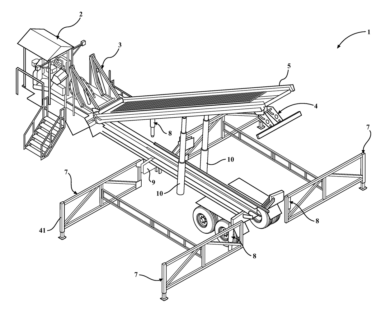
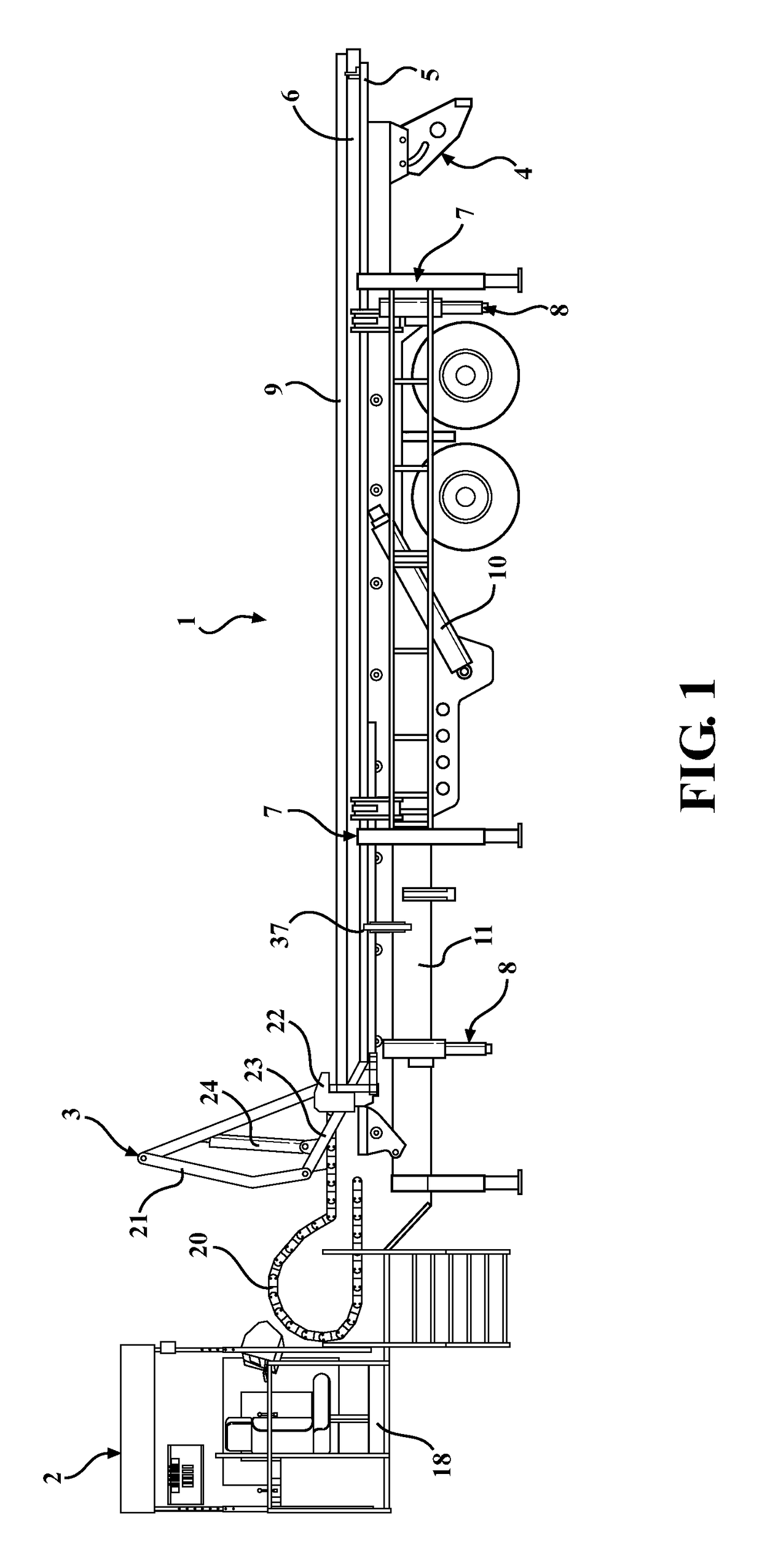
[0024]FIG. 1 is a side view of the pipe handling apparatus 1 in the lowered position. The pipe handling apparatus 1 includes an operator station 2, a hydraulic pipe pusher assembly 3, hydraulic bumper light bar 4, hydraulic pipe gates 5, hydraulic telescoping pipe table 6, hydraulic pipe racks 7, hydraulic leveling jacks 8, hydraulic pipe loader 9, main lift hydraulic cylinder 10, and the trailer base 11.

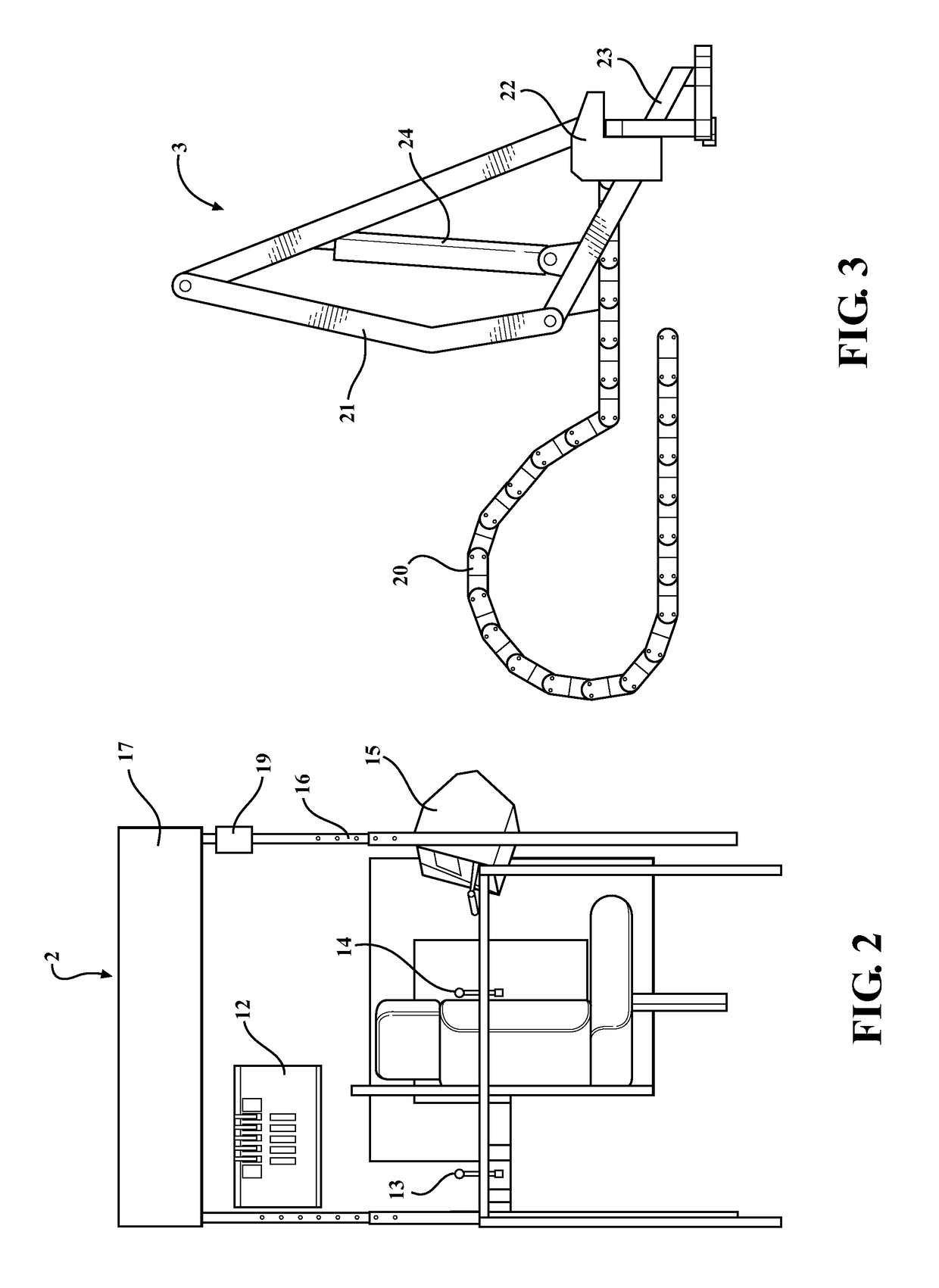
[0025]The operator station 2 is configured to allow the user to operate the pipe handing apparatus 1 from a single location. The operator station 2 has complete control over all hydraulically driven aspects of this pipe handling apparatus 1. FIG. 2 is a side view of the operator station 2 from side view. As depicted in FIG. 2, the operator station 2 may include hydraulic controls 12 to maneuver the hydraulic leveling jacks 8 that may be used to level the entire apparatus 1 to the contours of a specific location. The hydraulic controls 12 may additionally be configured to control the...


PUM


Abstract

A pipe handling apparatus comprising an operator station, a hydraulic pipe pusher assembly, hydraulic bumper light bar, hydraulic pipe gates, hydraulic telescoping pipe table, hydraulic pipe racks, hydraulic leveling jacks, hydraulic pipe loader, main lift hydraulic cylinder, and the trailer base.

Description

FIELD OF THE INVENTION[0001]This present invention relates to a pipe handling apparatus capable of manipulating up to sixteen (16) joints of pipe at a time and other tubular items that are commonly maneuvered on an oil and gas well site.BACKGROUND[0002]In the oil and gas industry, pipe and other tubular items are regularly hoisted vertically from the pipe racks on the ground to a work basket on the derrick which is typically 5 to 37 feet above the ground depending on the type of rig used. The pipe is then typically run down the well by the snubbing unit or workover rig from the work basket. There are also occasions when the process is reversed and the pipe must be retrieved from the work basket back down to the ground and placed on pipe racks.[0003]The oil and gas industry is a hazardous occupation. The need for reliable and safe manipulation of pipe and other tubular items is significantly warranted to maintain a safe work environment for all workers on the well site. In addition, ...

Claims


Application Information

Patent Timeline
Patent Type & Authority Patents(United States)
IPC IPC(8): E21B19/00E21B19/15
CPCE21B19/15
Inventor MOLSKI, TAMMY SUE
Owner MOLSKI TAMMY SUE
Why Eureka
Try Eureka