Photon counting x-ray detector

a detector and photon counting technology, applied in the field of x-ray detectors, can solve problems such as inability to accurately determine correction factors, and achieve the effect of improving dynamic range and accurate determination of x-ray radiation

Active Publication Date: 2017-04-18
KONINKLJIJKE PHILIPS NV
View PDF10 Cites 5 Cited by
  • Summary
  • Abstract
  • Description
  • Claims
  • Application Information

AI Technical Summary

Benefits of technology

[0004]It is an object of the invention to provide means that allow for a more accurate determination of X-radiation and an improved dynamic range.
[0025]The X-ray detector, the method, and the imaging system according to the invention have the advantage that flux related influences on the sensor signals provided by the sensor unit(s) can dynamically be corrected for because a flux signal is measured in parallel. This allows for example to improve the linearity of the detector output, or to resolve ambiguities that may occur in the raw sensor signals, e.g. due to a paralyzable detector behavior where the input count rate cannot be identified without ambiguity from the measured count rate.
[0028]The aforementioned alignment of the sensor unit and the flux sensor with respect to the main direction of X-ray incidence implies that (most or all of) the X-ray photons which impinge onto the sensor unit will also hit the flux sensor (if they are not beforehand absorbed in the sensor unit) or vice versa (in the less preferred case that the flux sensor is arranged in front of the sensor unit). The flux sensor will hence be exposed to the same part of the incident X-radiation as the sensor unit, which allows to correct the sensor signals individually in a spatially resolved way.
[0036]The data processing system (particularly the above mentioned processing circuit, if present) may preferably be adapted to count pulses of sensor signals generated by (single) X-ray photons. Thus a pulse counting (or “photon counting”) X-ray detector is provided which achieves a high accuracy. Due to hardware limitations, such a pulse counting detector is however prone to problems like non-linearities and saturation at high pulse rates. It is therefore particularly favorable that an X-ray detector according to the present invention allows for a flux related correction of sensor signals.

Problems solved by technology

A problem of this approach is that the behavior of the detector may drift over time such that the determined correction factors may become inappropriate.

Method used


Image

  • Photon counting x-ray detector
  • Photon counting x-ray detector
  • Photon counting x-ray detector

Examples


Embodiment Construction

[0046]Photon counting spectral CT faces the challenges of having to cope with very high X-ray flux rates, conditions under which even the best counting detectors build from CdTe or CZT behave in an intrinsically non-linear way due to pulse-pileup and dead-time effects. Depending on the detector electronics the behavior of the detectors can be modeled by the paralyzable or non-paralyzable detector behavior. In both cases the deviations from linearity are small as long as the rates remain smaller than the inverse deadtime but behave very differently around or above that level.

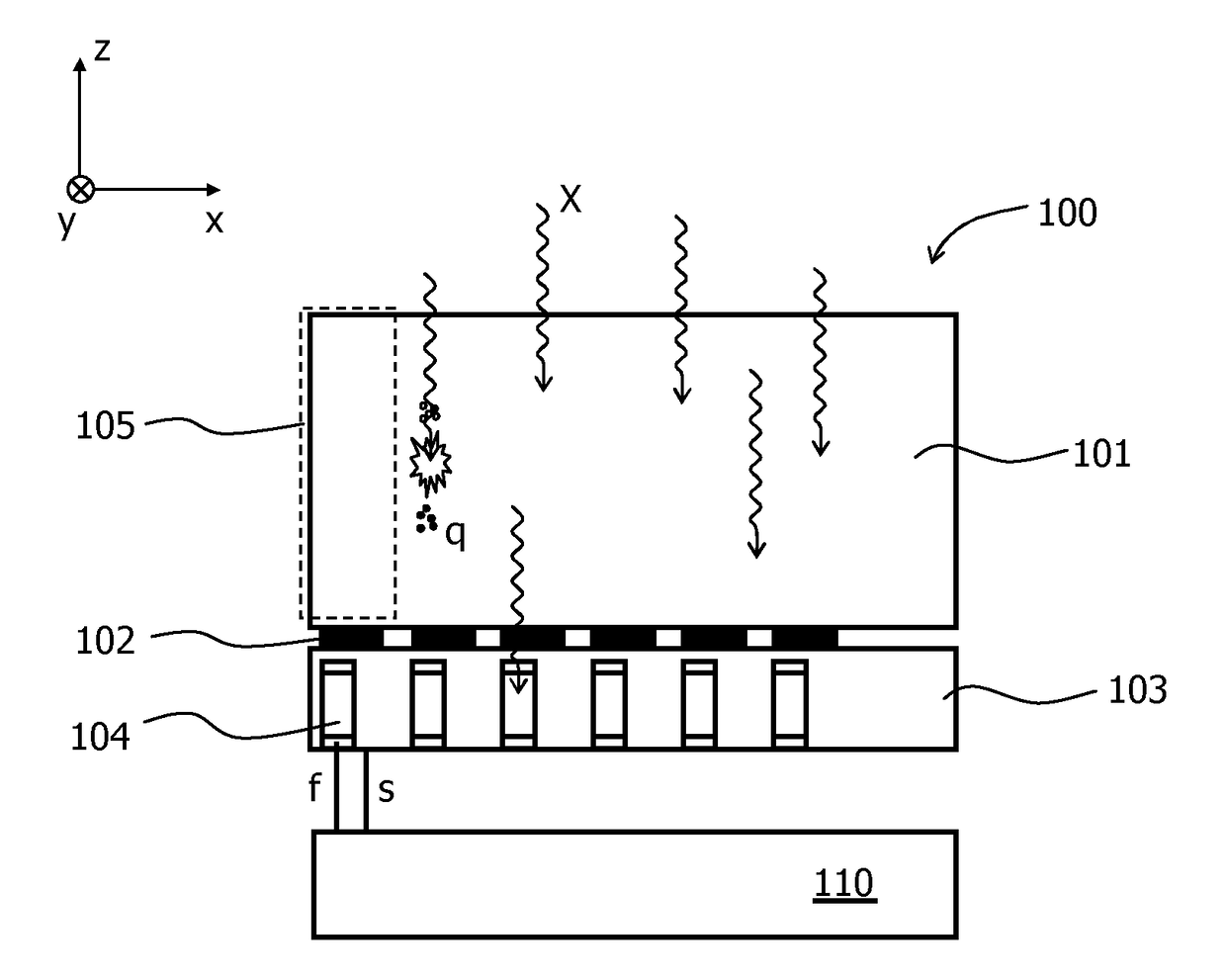
[0047]For example, the output count rate m of a paralyzable detector is a function of the input count rate r (number of incident X-ray photons per time) and a parameter τ which is related to the width of the pulses generated by the detector. It is theoretically given by the formula

m=rexp(−r·τ).

[0048]FIG. 1 shows the curve corresponding to this formula, which has a maximum at rmax=1 / τ. For one measurement of the o...


PUM

PropertyMeasurementUnit
distanceaaaaaaaaaa
spectrally resolved photon counting CTaaaaaaaaaa
volumeaaaaaaaaaa

Abstract

The invention relates to a method and an X-ray detector (100) for detecting incident X-ray photons (X). The X-ray detector (100) comprises at least one sensor unit (105) in which X-ray photons (X) are converted into sensor signals (s) and at least one flux sensor (104) for generating a flux signal (f) related to the flux of photons (X). The sensor signals (s) are corrected based on the flux signal (f). In a preferred embodiment, the sensor signals (s) represent a spectrally resolved pulse counting. The flux sensor (104) may be integrated into an ASIC (103) that is coupled to the sensor unit (105).

Description

CROSS-REFERENCE TO PRIOR APPLICATIONS[0001]This application is the U.S. National Phase application under 35 U.S.C. §371 of International Application No., PCT / IB2013 / 055817, filed on Jul. 15, 2013, which claims the benefit of U.S. Provisional Patent Application No. 61 / 682,344, filed on Aug. 13, 2012. These applications are hereby incorporated by reference in their entirety herein.FIELD OF THE INVENTION[0002]The invention relates to an X-ray detector and a method for the detection of incident X-ray photons. Moreover, it relates to an imaging system comprising such an X-ray detector.BACKGROUND OF THE INVENTION[0003]The U.S. Pat. No. 7,268,354 B2 discloses an X-ray detector with a plurality of detector elements for counting incident X-ray photons. In order to improve the linearity of the detector elements, correction factors are determined in advance. A problem of this approach is that the behavior of the detector may drift over time such that the determined correction factors may becom...

Claims


Application Information

Patent Timeline
Patent Type & Authority Patents(United States)
IPC IPC(8): H05G1/60G01T1/24G01N23/04
CPCG01T1/247G01N23/046G01T1/248G01T1/171
Inventor ROESSL, EWALDHEINER, DAERRSTEADMAN BOOKER, ROGER
Owner KONINKLJIJKE PHILIPS NV
Why Eureka
Try Eureka