Display device and electronic apparatus

a technology of electronic equipment and display device, which is applied in the direction of instruments, computing, electric digital data processing, etc., can solve the problems of reducing increasing the power consumption of the backlight, and deteriorating the display quality, so as to reduce the current value of the backlight, reduce power consumption, and increase luminance

Active Publication Date: 2017-04-18
JAPAN DISPLAY INC
View PDF29 Cites 2 Cited by
  • Summary
  • Abstract
  • Description
  • Claims
  • Application Information

AI Technical Summary

Benefits of technology

The present invention relates to a display device that reduces power consumption and improves display quality. The display device includes a display panel with alternating rows of sub-pixels, where the fourth sub-pixels are added to the first and second columns. The display device also uses a column inversion driving method to suppress charge and discharge in data lines and further reduce power consumption. Additionally, the display device performs driving by the scan lines in a way that reduces crosstalk and improves display quality. Overall, the display device achieves high definition with reduced power consumption and improved display quality.

Problems solved by technology

However, an increase in the resolution reduces an aperture ratio, and thus increases necessity for an increase in luminance of a backlight to achieve high luminance, which causes a problem of an increase in power consumption of the backlight.
H05-43118 to further suppress the power consumption can cause what is called crosstalk that reduces (deteriorates) display quality.

Method used


Image

  • Display device and electronic apparatus
  • Display device and electronic apparatus
  • Display device and electronic apparatus

Examples


first modification

3-1. First Modification

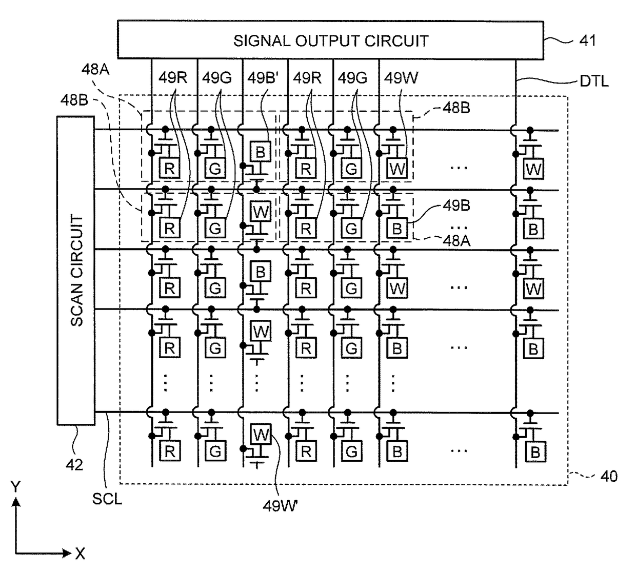
[0122]FIG. 18 is a conceptual diagram of an image display panel and an image display panel drive circuit of a display device according to a first modification of the present embodiment. In the display device according to the first modification of the present embodiment, a scan line SCL coupled to sub-pixels 49R′, 49G′, 49B′, 49R, 49G, and 49B, and a scan line SCL coupled to sub-pixels 49R′, 49G′, 49W′, 49R, 49G, and 49W are alternately arranged with pixels 48A and 48B in the same row interposed therebetween. The sub-pixels 49 in the third columns and adjacent to each other in the direction along the row direction are arranged so that the third sub-pixels 49B′ and the fourth sub-pixels 49W are alternately arranged in the same row of the third columns. Otherwise, the sub-pixels 49 in the third columns and adjacent to each other in the direction along the row direction are arranged so that the third sub-pixels 49B and the fourth sub-pixels 49W′ are alternately ar...

second modification

3-2. Second Modification

[0124]FIG. 19 is a diagram illustrating a pixel array of an image display panel according to a second modification of the present embodiment. In pixels 48A and pixels 48B of this image display panel 30, a first column includes white first sub-pixels 49W arranged therealong; a second column is arranged as a column next to the corresponding first column and includes green second sub-pixels 49G arranged therealong; and a third column is arranged between the first column and the second column. The first, second, and third columns are iteratively arranged. In third columns, blue third sub-pixels 49B and red fourth sub-pixels 49R are alternately arranged in the row direction. Further, in the same columns of the third columns, the third sub-pixels 49B and the fourth sub-pixels 49R are alternately arranged in the column direction. Such an arrangement increases the luminance of the white first sub-pixels 49W, thus allowing the image display panel to be brighter.

third modification

3-3. Third Modification

[0125]FIG. 20 is a diagram illustrating a pixel array of an image display panel according to a third modification of the present embodiment. In pixels 48A and pixels 48B of this image display panel 30, a first column includes red first sub-pixels 49R arranged therealong; a second column is arranged as a column next to the corresponding first column and includes green second sub-pixels 49G arranged therealong; and a third column is arranged as a column next to the corresponding second column. The first, second, and third columns are iteratively arranged. In third columns, blue third sub-pixels 49B and yellow fourth sub-pixels 49Y are alternately arranged in the row direction. Further, in the same columns of the third columns, the third sub-pixels 49B and the fourth sub-pixels 49Y are alternately arranged in the column direction. A yellow color filter, for example, is disposed between a fourth sub-pixel 49Y and the image observer. Such an arrangement allows the ...


PUM

PropertyMeasurementUnit
luminanceaaaaaaaaaa
power consumptionaaaaaaaaaa
currentaaaaaaaaaa

Abstract

According to an aspect, a display device includes an image display panel, data lines, and scan lines. The image display panel includes arrays of pixels including a plurality of sub-pixels. The arrays of pixels include cyclically arranged columns of first columns each of which includes first sub-pixels, second columns that include second sub-pixels, and third columns. Third sub-pixels and fourth sub-pixels are alternately arranged in the third columns in the direction along the third columns, and are alternately arranged in a direction along the row in the same row of the third columns. Each of the scan lines is coupled to either of the third sub-pixels adjacent thereto or the fourth sub-pixels adjacent thereto, as sub-pixels to be selected thereby.

Description

CROSS-REFERENCE TO RELATED APPLICATIONS[0001]This application claims priority from Japanese Application No. 2013-010563, filed on Jan. 23, 2013, and Japanese Application No. 2013-251553, filed on Dec. 4, 2013, the contents of which are incorporated by reference herein in its entirety.BACKGROUND[0002]1. Technical Field[0003]The present disclosure relates to a display device and to an electronic apparatus including the display device.[0004]2. Description of the Related Art[0005]Recent years have seen a growing demand for display devices for use in, for example, mobile devices such as a mobile phone and electronic paper. In a display device, one pixel includes a plurality of sub-pixels, each of which emits light of a different color. The single pixel displays various colors by switching on and off display of the sub-pixels. Such display devices have been improved year after year in display properties such as resolution and luminance. However, an increase in the resolution reduces an ap...

Claims


Application Information

Patent Timeline
Patent Type & Authority Patents(United States)
IPC IPC(8): G09G3/36G02F1/136G09G5/02G06F3/041G06F3/044G02F1/1362
CPCG06F3/041G06F3/044G06F3/0412G09G3/3614G09G3/3648G02F1/136213G02F2201/52G09G5/02G09G2300/0452G09G2300/0491G09G2300/0495G09G2320/0209G09G2320/0276G09G2340/06G06F2203/04103G06F3/0446G06F3/0445
Inventor YAMAGUCHI, HIDEMASAKABE, MASAAKI
Owner JAPAN DISPLAY INC
Why Eureka
Try Eureka