

Vibration element, vibrator, vibration device, electronic device and moving object
a technology of vibration element and vibration device, which is applied in the direction of speed measurement using gyroscopic effects, instruments, surveying and navigation, etc., can solve the problems of insufficient mechanical strength, insufficient impact absorption and relaxation of each beam, and insufficient impact resistance at the time of falling, etc., to achieve high reliability
- Summary
- Abstract
- Description
- Claims
- Application Information
AI Technical Summary
Benefits of technology
Problems solved by technology
Method used
Image

Examples
first embodiment
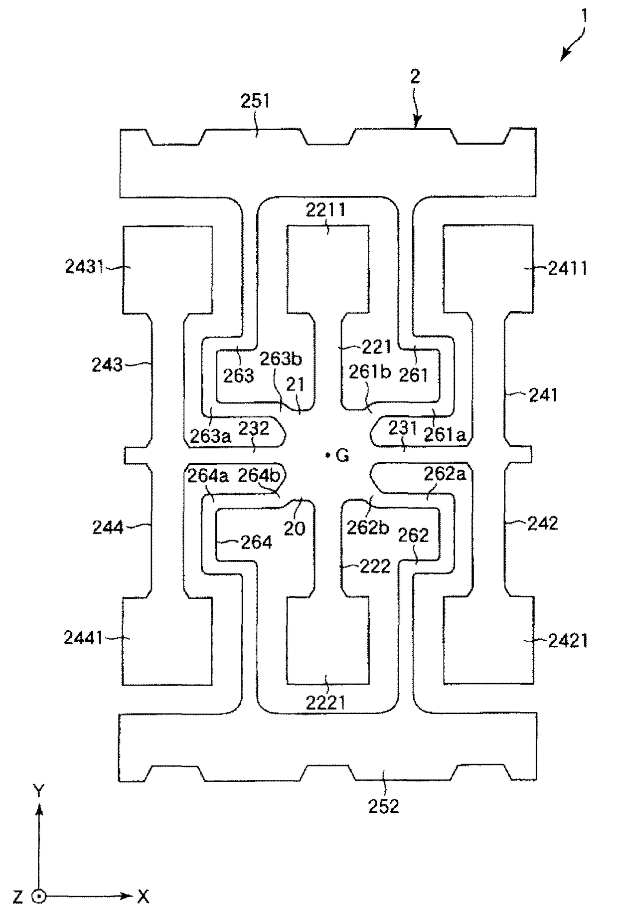
[0046]First, a vibration element according to a first embodiment of the invention will be described.
[0047]FIG. 1 is a plan view illustrating a vibration element according to the first embodiment of the invention. FIG. 2 is an enlarged plan view illustrating the vicinity of the central portion of the vibration element shown in FIG. 1. FIG. 3 is a plan view illustrating electrodes included in the vibration element shown in FIG. 1. FIG. 4 is a plan view (perspective view) illustrating electrodes included in the vibration element shown in FIG. 1. FIGS. 5A and 5B are diagrams illustrating operations of the vibration element shown in FIG. 1. Meanwhile, hereinafter, for convenience of description, the sheet's front side of FIGS. 1 and 2 is also called an “upper side”, and the sheet's deep side is also called a “lower side”. In addition, in FIGS. 1, 2 and 6, for convenience of description, the electrodes are not shown.
Basic Structure of Vibration Element
[0048]A vibration element 1 shown in ...
second embodiment
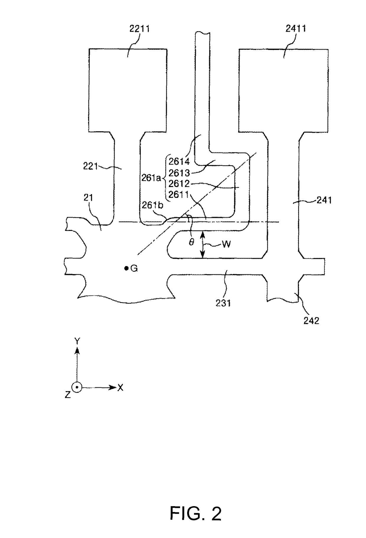
[0092]Next, a vibration element according to a second embodiment of the invention will be described.
[0093]FIG. 6 is an enlarged plan view illustrating the vicinity of the central portion of a vibrator according to the second embodiment of the invention. Meanwhile, in FIG. 6, for convenience of description, electrodes are not shown.
[0094]Hereinafter, the second embodiment will be described with focus on a difference from the aforementioned embodiment, and the description of the same particulars will not be given below.
[0095]The second embodiment is the same as the aforementioned first embodiment, except for different configurations of the inclination portions of the respective beams. Meanwhile, in FIG. 6, the same components as those of the embodiment mentioned above are denoted by the same reference numerals and signs. In addition, since the shapes of the first to fourth beams 261 to 264 are the same as each other, the first beam 261 will be representatively described below, and the...
PUM
 Abstract
Description
Claims
Application Information