Device for testing mechanical seal performance

a mechanical seal and performance technology, applied in the field of sealing sealing testing technology, can solve the problems of large axial force, affecting the service life of the bearing, and difficult to symmetrical two groups of mechanical seals, and achieve the effect of improving the workability of on-site installation

Active Publication Date: 2017-04-25
NANJING FORESTRY UNIV
View PDF19 Cites 3 Cited by
  • Summary
  • Abstract
  • Description
  • Claims
  • Application Information

AI Technical Summary

Benefits of technology

[0009]An object of the present invention is to provide a device for testing mechanical seal performance, which is capable of achieving automatic symmetric positioning of two groups of mechanical seals to be tested with respect to the center cross section of the working chamber, and an equal regulation of the end-face specific pressure, avoiding an additionally axial force caused by the medium while experimenting, simultaneously improving on-site installation workability and measurement accuracy of the end-face friction torque, which is adapted for performance researches and type tests of mechanical seal with large diameter under high pressure.

Problems solved by technology

Large axial force is harmful to the service life of the bearing.
However, it is very difficult for the two groups of mechanical seals to be symmetrical with the center cross section of the working chamber at the initial position.
However, the main shaft and the driving connecting structure are still complex.
However, it is very inconvenient for installing the mechanical seal to be tested, and especially it is very difficult to meet the requirements of quick assembly and disassembly during type experiments.
Therefore, not only the experimental process is complex, but also the accuracy of the test is reduced.
However, it is easy for the stress shaft with smaller diameter to generate plastic deformation, even fracture.

Method used


Image

  • Device for testing mechanical seal performance
  • Device for testing mechanical seal performance
  • Device for testing mechanical seal performance

Examples


Embodiment Construction

[0042]The present invention is further illustrated combined with the following drawings and implements.

[0043]To further understand the contents, characteristics and effects of the present invention are described in detail as follows combined with the drawings:

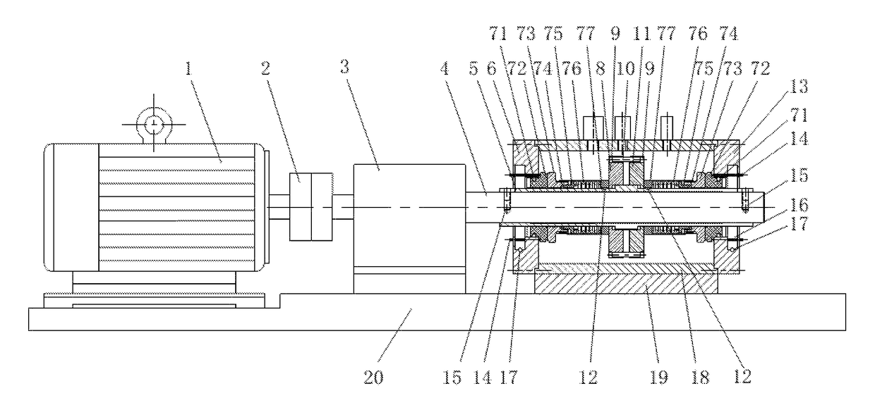
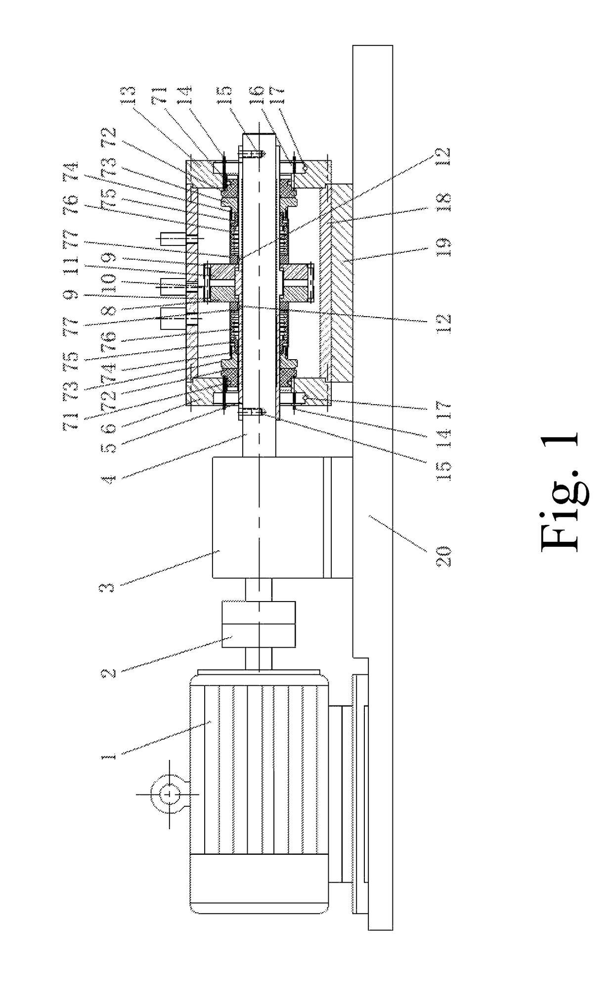
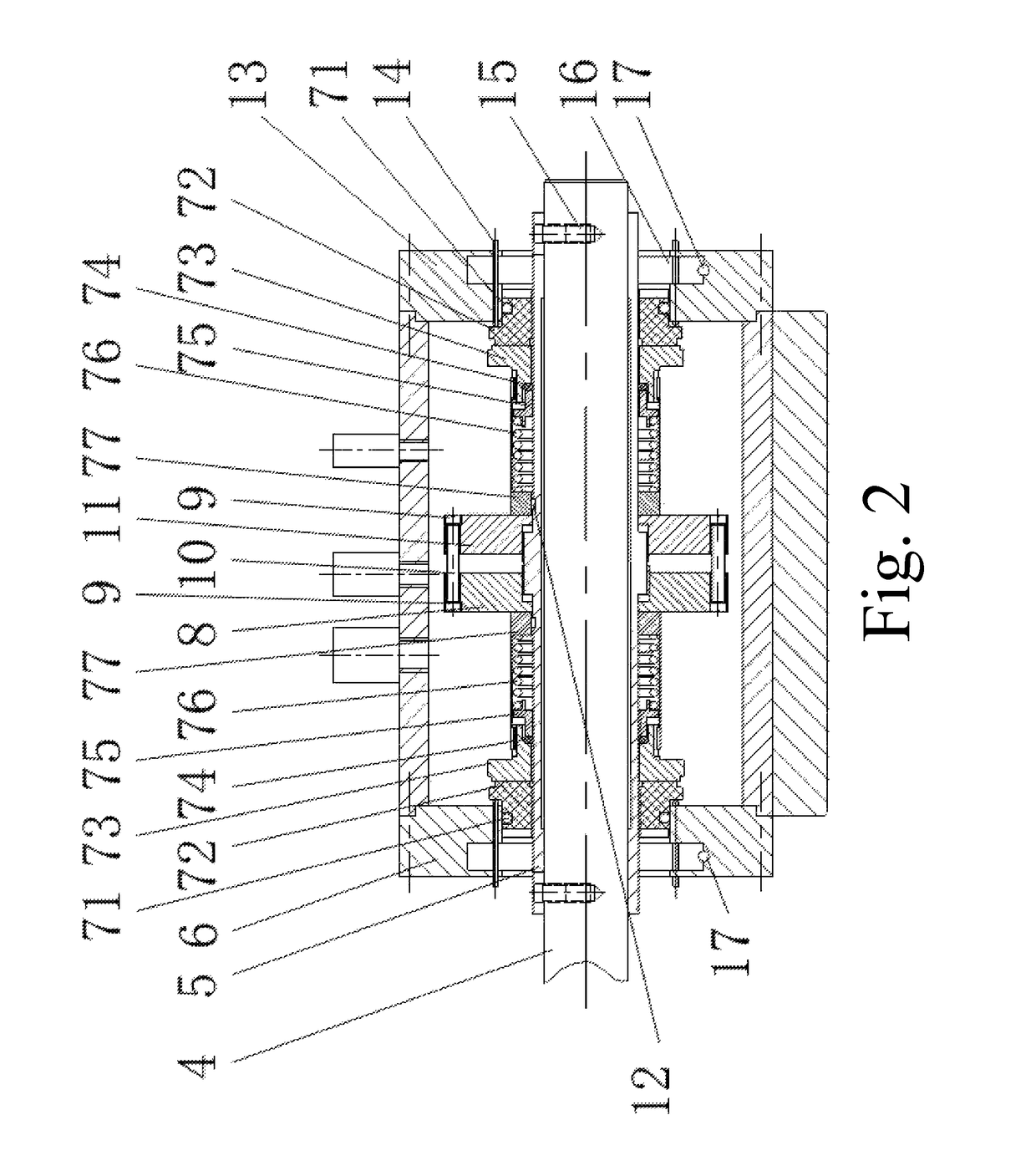
[0044]FIGS. 1 and 2 show a device for testing a mechanical seal performance which comprises a motor 1, a coupling 2, a bearing box 3, a main shaft 4, drive pins 15, a shaft sleeve 5, a left end cover 6, technological hole plugs 24, technological shafts 22, axial force sensors 14, two groups of mechanical seals to be tested (a stationary O-ring 71 a stationary ring 72, a rotating ring 73, a rotating O-ring 74, a support ring 75, a spring 76, a rotating ring seat 77), guide flat keys 12, a left nut 8, a right nut 11, short pins 10, short pin hole plugs 9, a working chamber 18, a right end cover 13, a carriage 19 and a stand 20.

[0045]The shaft sleeve 5 has a symmetrical structure with respect to a center cross section. Two U-shape...


PUM

PropertyMeasurementUnit
mechanical seal performanceaaaaaaaaaa
rotationaaaaaaaaaa
forceaaaaaaaaaa

Abstract

A device for testing mechanical seal performance includes a main shaft (4), a working chamber (18) with two end covers (6, 13) respectively located at two ends thereof, and two groups of mechanical seals to be tested (7); wherein a shaft sleeve (5) and the main shaft (4) form a clearance fit and penetrate through the end covers (6, 13) at two ends of the working chamber (18) together; the shaft sleeve (5) extends outside U-shaped openings (23) which are arranged at two ends of the end covers (6, 13) and arranged on the same generatrix; driven pins (15) are arranged on the locations of the main shaft (4) corresponding to the U-shaped openings (23); the middle part of the shaft sleeve (5) is provided with two segments of threads having the same thread pitch and opposite rotating directions.

Description

CROSS REFERENCE OF RELATED APPLICATION[0001]This is a U.S. National Stage under 35 U.S.C 371 of the International Application PCT / CN2013 / 090626, filed Dec. 27, 2013, which claims priority under 35 U.S.C. 119(a-d) to CN 201310162335.9, filed May 6, 2013.BACKGROUND OF THE PRESENT INVENTION[0002]Field of Invention[0003]The present invention belongs to the field of sealing testing technology, and more particularly relates to a device for testing mechanical seal performance which has no additional axial force and is capable of accurately testing the torque. The device is adapted for testing mechanical seal performance of the rotating machinery with large diameter including large compressors and centrifugal pumps for conveying high pressure media, or stirred tank reactors for mixing high pressure media.[0004]Description of Related Arts[0005]It is required of mechanical seals with stable performance to meet the demand of large-scale, integration, and long-term operation of the production d...

Claims


Application Information

Patent Timeline
Patent Type & Authority Patents(United States)
IPC IPC(8): G01L3/02G01M13/00G01M3/26G01M3/28
CPCG01L3/02G01M3/26G01M3/2869G01M13/005
Inventor SUN, JIANJUNTU, QIAOANHU, QIONGMA, CHENBOYU, QIUPINGZHOU, MIN
Owner NANJING FORESTRY UNIV
Why Eureka
Try Eureka