Brushless motor

a brushless motor and motor body technology, applied in the direction of windings, mechanical energy handling, magnetic circuit shapes/forms/construction, etc., can solve the problems of increasing manufacturing costs, difficult to change the wire binding pattern of the coil without, cumbersome wire binding work for the connecting wire of the coil, etc., to reduce the time and manufacturing cost of the wire binding process, and simplify the work of the coil wire binding process. simple and optimized

Active Publication Date: 2017-04-25
SANYO DENKI CO LTD
View PDF26 Cites 0 Cited by
  • Summary
  • Abstract
  • Description
  • Claims
  • Application Information

AI Technical Summary

Benefits of technology

[0011]In view of the aforementioned problems, the present invention provides a brushless motor capable of reducing a wire binding process time and a manufacturing cost by simplifying and optimizing the coil wire binding work.
[0012]In addition, the present invention provides a brushless motor capable of changing the wire binding pattern of the coil in a simple manner just by changing the wire binding board without changing the coil structure and handling of the connecting wire.
[0016]In the brushless motor according to the present invention, it is not necessary to individually bind a plurality of connecting wires of the coils. Therefore, it is possible to simplify and optimize a coil wire binding work and reduce a wire binding process time and a manufacturing cost.
[0017]In the brushless motor according to the present invention, it is possible to change the wire binding pattern of the coil in a simple manner just by changing the wire binding board without changing the coil structure and handing of the connecting wire of the coil.

Problems solved by technology

Therefore, a wire binding work for the connecting wire of the coil becomes cumbersome and increases a manufacturing cost.
However, in the technique disclosed in JP 2001-327110 A, it is difficult to change a wire binding pattern of the coil without changing a coil structure or a wiring structure of the connecting wire to the electric conductor.
This further causes cumbersomeness of the coil wire binding work.

Method used


Image

  • Brushless motor
  • Brushless motor
  • Brushless motor

Examples


Embodiment Construction

[0021]Hereinafter, a brushless motor according to the present embodiment will be described with reference to the accompanying drawings.

[0022]In the brushless motor according to the present embodiment, an end portion of a coil and a circuit board are electrically connected to each other through a connecting terminal and a wire binding board having a wire binding pattern of the coil. According to the present embodiment, it is possible to provide a brushless motor capable of changing the wire binding pattern of the coil in a simple manner just by changing a wire binding board without changing a coil structure and handling of the connecting wire of the coil.

[Configuration of Brushless Motor]

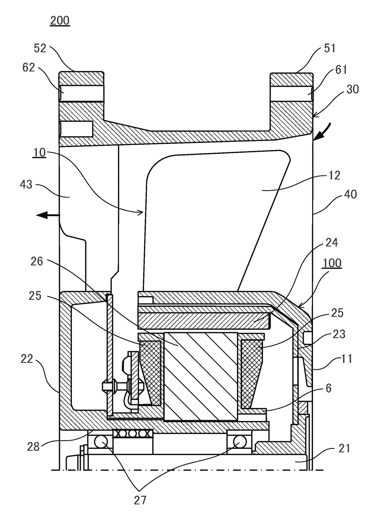
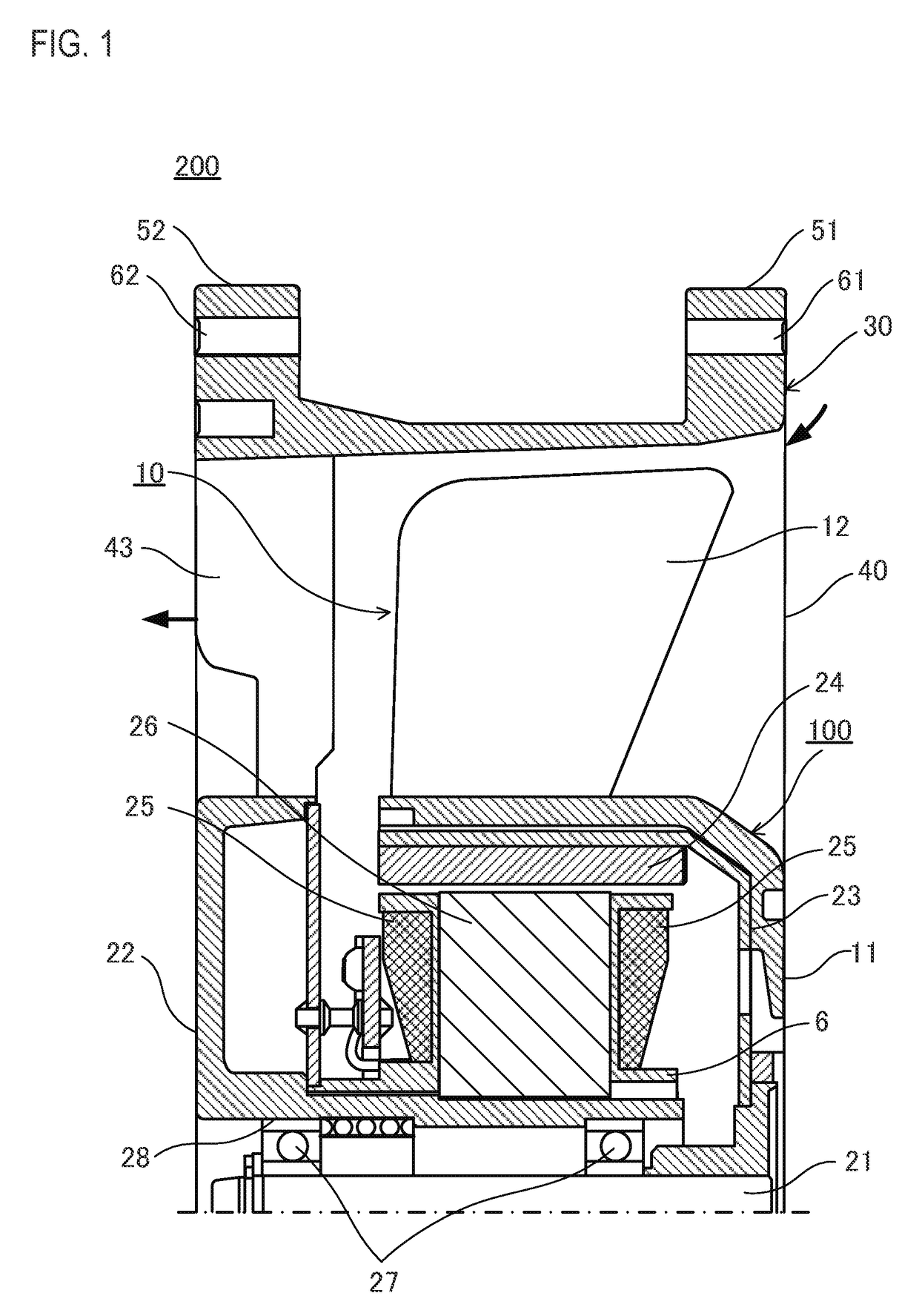
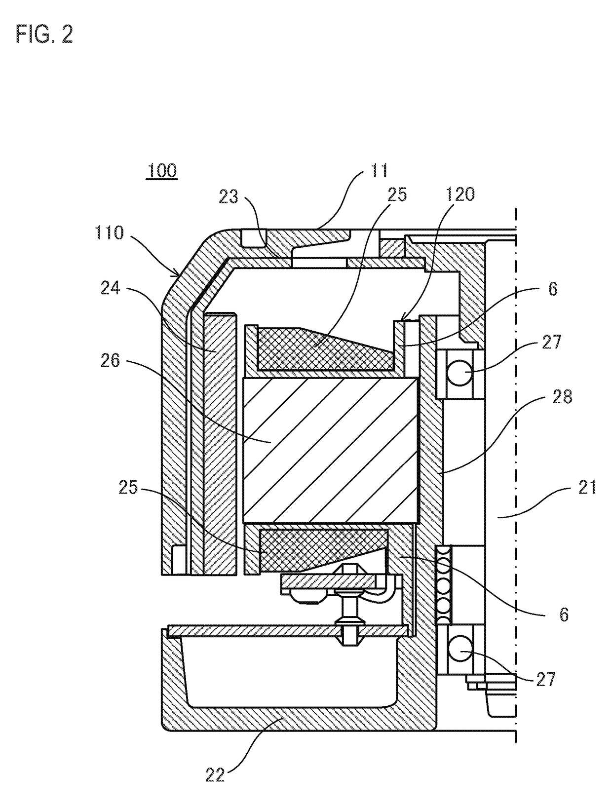
[0023]First, an axial flow fan obtained by applying the brushless motor according to the present embodiment will be described with reference to FIGS. 1 and 2. FIG. 1 is a cross-sectional view illustrating an axial flow fan obtained by applying the brushless motor according to the present embodiment. ...


PUM


Abstract

A brushless motor includes a stator as an armature where a plurality of coils is housed and a rotor as a magnetic exciter having a permanent magnet, wherein an end portion of the coil housed in a slot of a stator stack is inserted into a wire binding board having a wire binding pattern of the coil, the end portion of the coil is soldered to a land of the wire binding board, and the wire binding board and a circuit board are electrically conducted to each other through an connecting terminal.

Description

CROSS-REFERENCE TO RELATED APPLICATION[0001]This application claims priority to Japanese Application No. 2012-137202, filed Jun. 18, 2012, the entirety of which is incorporated herein by reference.BACKGROUND[0002]1. Technical Field[0003]The present invention relates to a brushless motor having an improved coil wire binding structure inside a slot of a stator stack.[0004]2. Description of Related Arts[0005]A brushless motor includes an armature where a plurality of coils is wound and a magnetic exciter having a permanent magnet. Typically, an outer rotor type brushless motor is employed in an axial flow fan such as a cooling fan. In the outer rotor type brushless motor, an armature having a coil is provided as an inner stator, and a magnetic exciter having a permanent magnet is provided as an outer rotor in an outer circumference of the stator.[0006]The coil is housed in a plurality of slots formed in the stator stack. For example, in the case of a stator stack having twelve slots, i...

Claims


Application Information

Patent Timeline
Patent Type & Authority Patents(United States)
IPC IPC(8): H02K3/50H02K9/06H02K11/33H02K7/14H02K3/52
CPCH02K3/50H02K3/522H02K7/14H02K11/33H02K2203/03H02K2213/12H02K1/16H02K3/46H02K5/22
Inventor MIYABARA, YOSHINORIMARUYAMA, HARUHISASATOU, KEISAKAI, HARUKA
Owner SANYO DENKI CO LTD
Why Eureka
Try Eureka