Smoke exhaust system for a cooking appliance

a technology for exhaust systems and cooking appliances, applied in the field of cooking appliances, can solve problems such as objectionable odors in smoke, and achieve the effect of reducing smoke and associated odors

Active Publication Date: 2017-05-02
CONAIR CORP
View PDF38 Cites 69 Cited by
  • Summary
  • Abstract
  • Description
  • Claims
  • Application Information

AI Technical Summary

Benefits of technology

[0005]It is another object of the present invention to provide a cooking appliance having a smoke exhaust system for reducing smoke and associated foul odors expelled from the appliance during cooking.
[0010]According to yet another embodiment of the present invention, a method of reducing smoke and associated odors in a cooking appliance having an upper housing having a first heating surface and a lower housing having a second heating surface is provided. The method includes the steps of operatively connecting the upper housing with the lower housing such that the first heating surface is positioned in opposition to the second heating surface, and equipping the cooking appliance with a smoke reduction system including an air inlet adjacent to the first heating surface, an exhaust vent formed in the upper housing, and a fan disposed in the upper housing. The fan is configured to draw air through the inlet, into the upper housing, and expel the air through the exhaust vent.

Problems solved by technology

This smoke may contain objectionable odors.

Method used


Image

  • Smoke exhaust system for a cooking appliance
  • Smoke exhaust system for a cooking appliance
  • Smoke exhaust system for a cooking appliance

Examples


Embodiment Construction

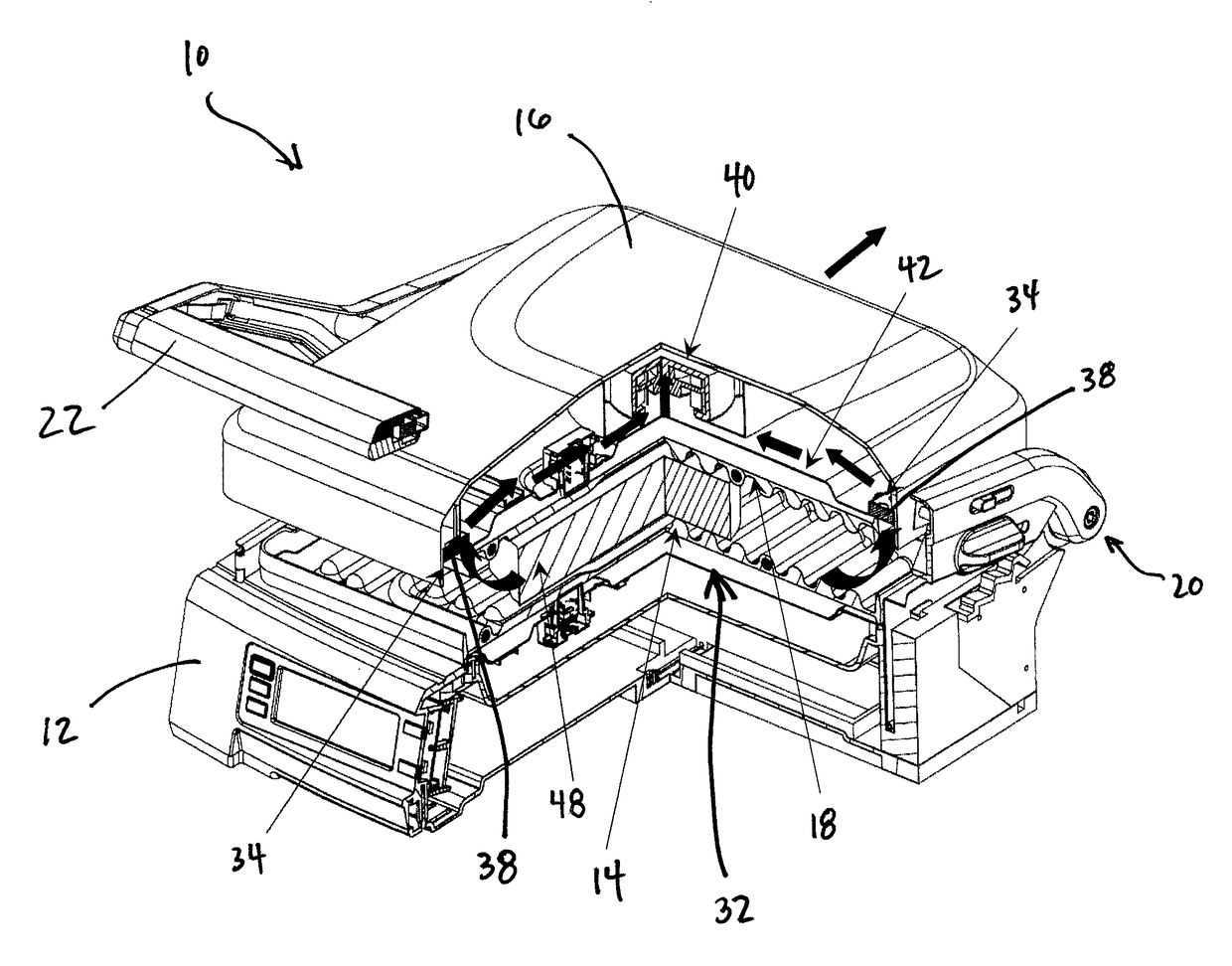
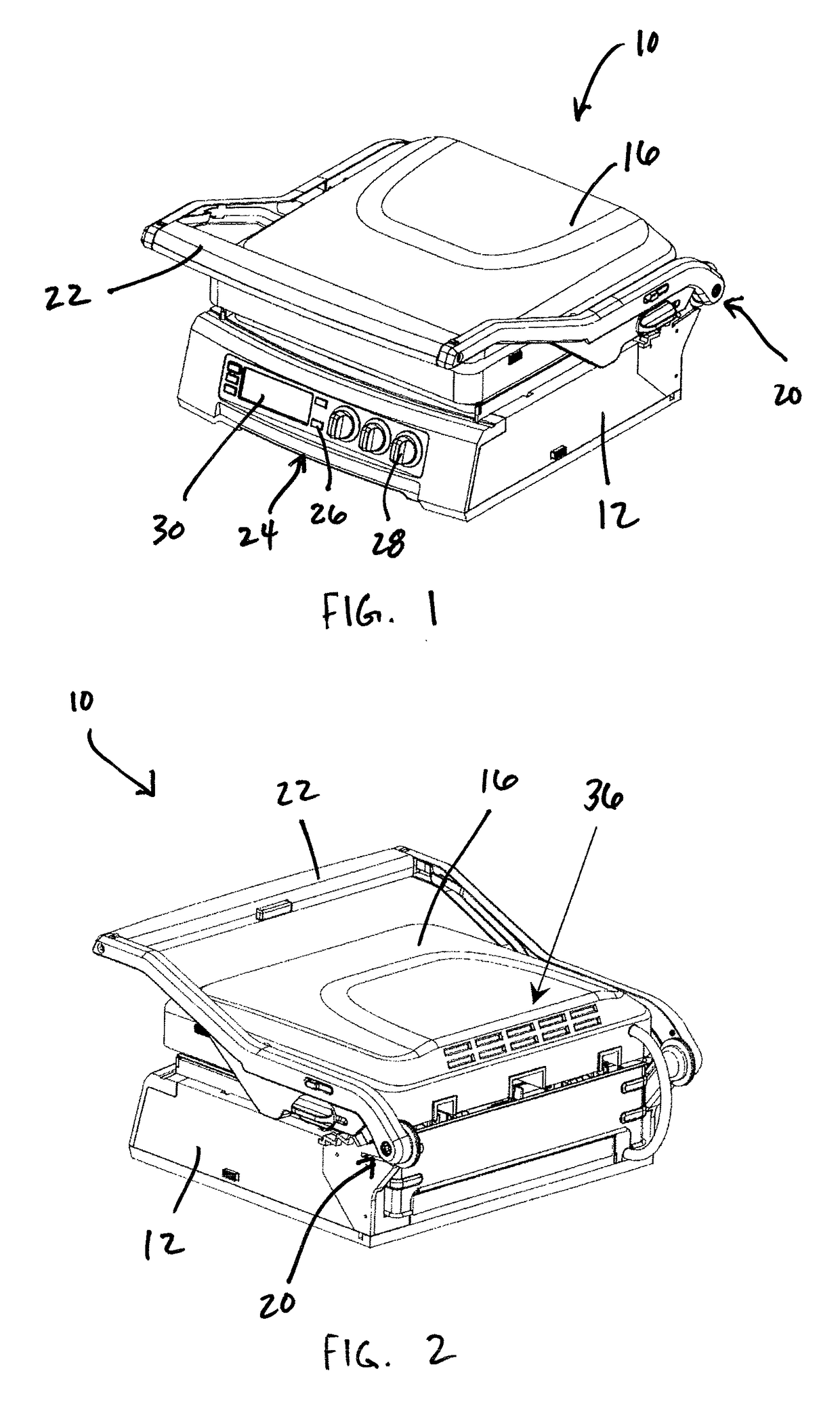
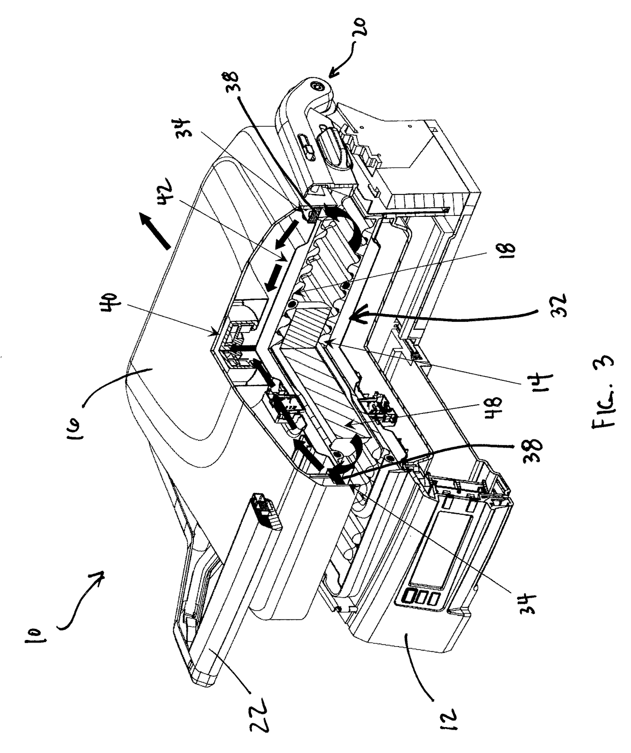
[0021]Referring to FIGS. 1 and 2, a cooking appliance 10 according to an embodiment of the present invention is shown. As shown therein, the cooking appliance 10 generally takes the form of a countertop grill and includes a lower housing 12 having a lower heating / cooking plate 14 and an upper housing 16 having an upper heating / cooking plate 18.

[0022]As best shown in FIG. 2, the upper housing 16 is operatively connected to the lower housing 12 at a rear hinge 20. A handle 22 is attached to the upper housing 16 and allows a user to raise and lower the upper housing 16, via rotation about the hinge 20, in order to selectively position the upper housing 16 in various positions in relation to the lower housing 12.

[0023]With further reference to FIGS. 1 and 2, the cooking appliance 10 includes a control panel 24 having an array of buttons 26 and rotatable knobs 28 that allow a user to select and set a variety of cooking and heating parameters, and an LCD screen 30 that allows a user to vi...


PUM

PropertyMeasurementUnit
electricalaaaaaaaaaa
areaaaaaaaaaaa

Abstract

A cooking appliance includes a lower housing having a lower heating surface, an upper housing operatively connected to the lower housing and having an upper heating surface, and a smoke exhaust system. The smoke exhaust system includes an air inlet in a lower surface of the upper housing adjacent to the upper heating surface, an exhaust vent formed in the upper housing, and a fan disposed in the upper housing. The fan is configured to draw air through the inlet, into the upper housing, and expel the air through the exhaust vent.

Description

FIELD OF THE INVENTION[0001]The present invention relates to cooking appliances and, more particularly, to a smoke exhaust system for a cooking appliance.BACKGROUND OF THE INVENTION[0002]Cooking appliances, and in particular electric cooking / grilling devices such as griddles, are known. One type of known grilling devices typically evidences a lower housing having a lower cooking surface and an upper housing having an upper cooking surface, wherein the cooking surfaces are typically heated by an electrical resistance heater. A handle attached to the upper housing allows a user to raise and lower the upper housing relative to the lower housing to accommodate a food item therebetween to be heated.[0003]While existing grilling devices are generally suitable for what is regarded as ordinary performance, there is room for improvement in terms of convenience and cleanliness. As will be readily appreciated, it is typical that smoke is generated during cooking due to the contact of food item...

Claims


Application Information

Patent Timeline
Patent Type & Authority Patents(United States)
IPC IPC(8): A47J37/00A47J36/38B01D46/00A47J37/06F24C15/20B01D46/10B01D53/04
CPCB01D46/0038A47J36/38A47J37/0611B01D46/10F24C15/2035B01D53/04B01D2253/102B01D2257/90B01D2258/0275
Inventor FUNG, KAM FAILAI, KIN MAN
Owner CONAIR CORP
Why Eureka
Try Eureka