

Rear fairing system for a vehicle
a technology for rear fairings and vehicles, applied in vehicle body streamlining, vehicle components, vehicle body, etc., can solve the problems of inconvenient use, inability to adjust the position of fairings, so as to reduce the damage of impact, facilitate door opening, and add resilience
- Summary
- Abstract
- Description
- Claims
- Application Information
AI Technical Summary
Benefits of technology
Problems solved by technology
Method used
Image

Examples
Embodiment Construction
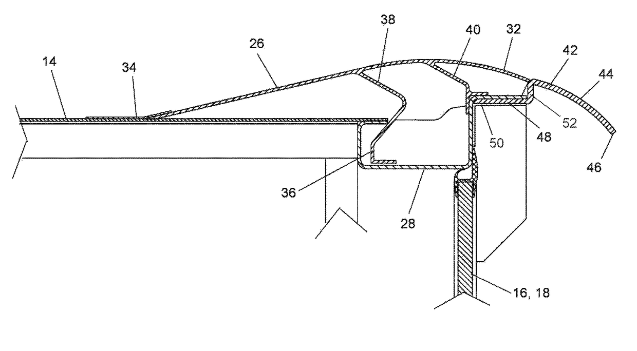
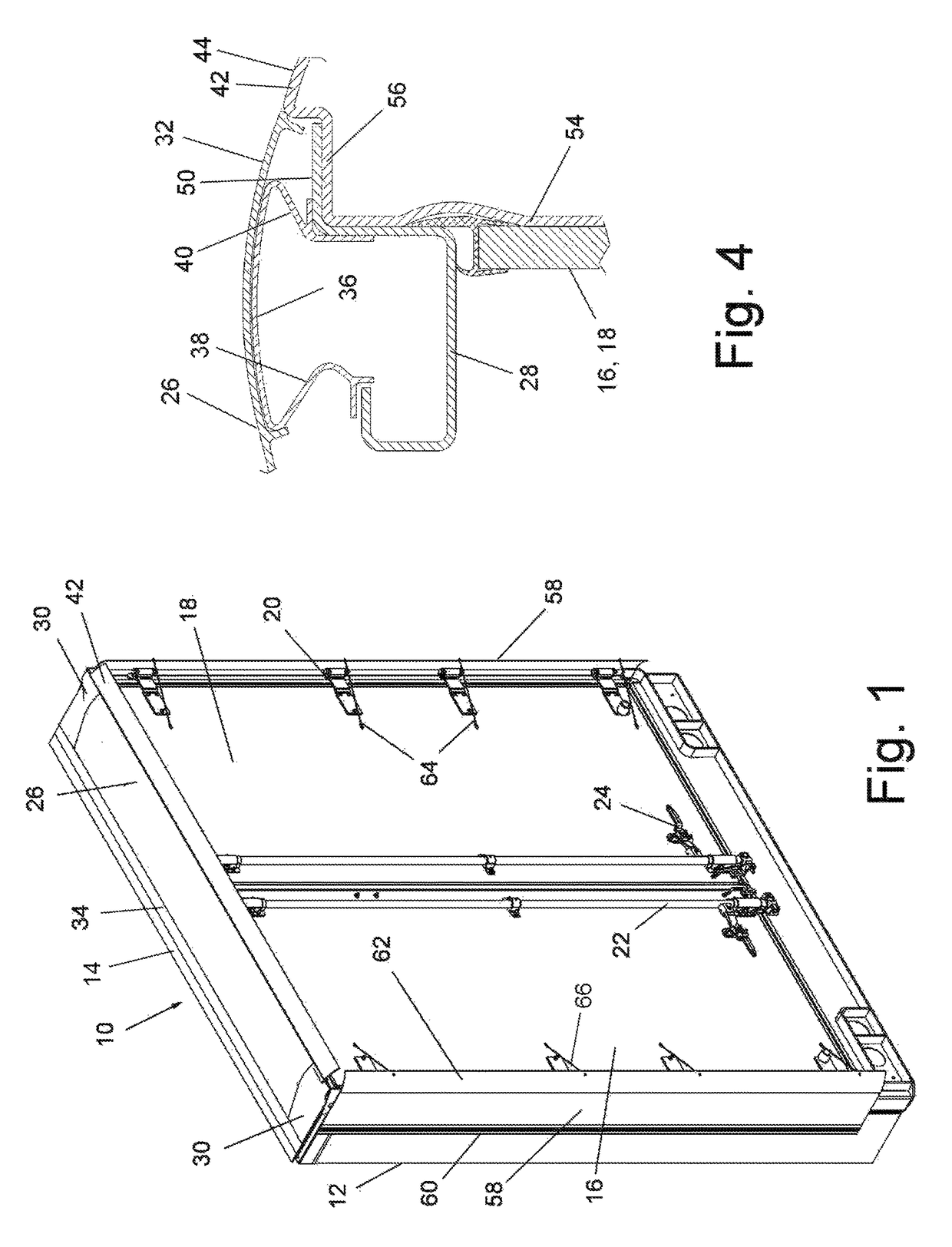
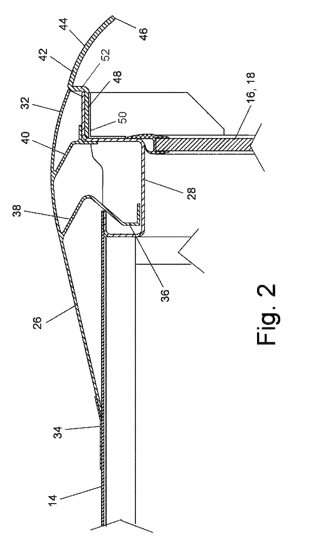
[0015]Turning to the drawings in detail, FIG. 1 illustrates the back end of a conveyance vehicle which may be a truck, semi-trailer, trailer or other cargo vehicle 10. Such devices typically include vertical sidewalls 12, a horizontal roof 14 extending between the vertical sidewalls 12 and rear doors 16, 18. The rear doors 16, 18 are hinged about vertical pivot axes typically defined by a series of hinges 20 attached to the frame of the vehicle at the vehicle sidewalls 12. Typical latching mechanisms 22, 24 are also illustrated. A rear fairing system is illustrated to extend across the roof 14 and to extend down the vertical sidewalls 12.
[0016]The fairing system includes a roof foil 26 on the vehicle roof 14. The roof foil 26 extends laterally across the roof 14 to the sidewalls 12. FIGS. 2 and 3 illustrate the same roof foil 26 in cross section. The roof foil 26 is associated with the top panel of the roof 14 and a horizontally extending vehicle frame 28 of the vehicle 10 which ext...
PUM
 Abstract
Description
Claims
Application Information