Radio wave transmitter and receiver for portable terminal

A technology for receiving equipment and terminals, which is applied to circuits, electrical components, telephone structures, etc., and can solve the problems of reduced sensitivity of sending calls and receiving calls.

Inactive Publication Date: 2004-05-12
LG ELECTRONICS INC
View PDF0 Cites 2 Cited by
  • Summary
  • Abstract
  • Description
  • Claims
  • Application Information

AI Technical Summary

Problems solved by technology

In this position, the sensitivity of sending and receiving calls is reduced

Method used


Image

  • Radio wave transmitter and receiver for portable terminal
  • Radio wave transmitter and receiver for portable terminal
  • Radio wave transmitter and receiver for portable terminal

Examples


Embodiment Construction

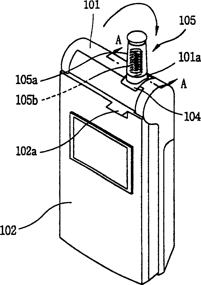
[0022] refer to image 3 and 4, the portable terminal according to one embodiment of the present invention includes a folding portion 102 hinged on the upper portion of the main body 101 for opening and closing. A mounting groove 101a is formed in the upper part of the main body at the part where the main body is hinged with the folding part. An upper portion of the mounting groove 101a is opened, and a lower portion thereof is connected to a printed circuit board P located inside the main body.

[0023] The insulating shaft 103 is installed in the installation groove 101 in the horizontal direction, and the rotating member 104 is installed on the shaft 103 which is horizontally cylindrical. More specifically, a circularly polarized feeder 111 (described below) is mounted on the inner peripheral surface of a shaft hole 104a formed in the center of the rotating member 104, and the shaft 103 is inserted into the shaft hole 104a. In order to turn the rotating part 104, the shaf...


PUM


Abstract

An electric wave transmitting and receiving apparatus of a portable terminal comprising: a rotating member axially installed in a mounting groove formed at an upper portion of a body to be rotated with a certain angle; a vertical polarization antenna installed at an upper of the rotating member, for rotating the rotating member around the axis by a pressure of a folder at the time of opening the folder of the portable terminal; an elastic member installed at one side of the rotating member, for placing the rotated vertical polarization antenna and the rotating member to original positions; a vertical polarization antenna connecting means for connecting the vertical polarization antenna to a printing circuit board mounted in the body; a circular polarization antenna installed at a side surface of the rotating member; and a circular polarization antenna connecting means for connecting the circular polarization antenna to the printing circuit board.

Description

technical field [0001] The present invention generally relates to wireless communication, in particular to a radio wave sending and receiving device for a wireless terminal. Background technique [0002] An antenna used by a portable terminal such as a cellular phone includes a vertically polarized antenna mounted outside a terminal body and a circularly polarized antenna mounted on a printed circuit board. These two antennas are used to send and receive audio and data. [0003] In a cellular phone, an antenna is used to convert a signal amplified by a high-frequency circuit therein into electromagnetic waves that may seriously affect the user's brain in the vicinity of the antenna. As the number of cellular phone users increases, so does the debate supporting the theory that these electromagnetic waves can harm the human body. [0004] figure 1 is a side view showing a portable terminal according to a related prior art, figure 2 is a side view showing a vertically pola...

Claims


Application Information

Patent Timeline
Patent Type & Authority Applications(China)
IPC IPC(8): H01Q1/08H01Q1/24H01Q21/28
CPCH01Q21/28H01Q1/242H01Q1/084H01Q1/245H01Q1/08H01Q1/24
Inventor 崔泰奎
Owner LG ELECTRONICS INC
Why Eureka
Try Eureka