
Umbrella canopy tilt mechanism

a technology of tilt mechanism and umbrella, which is applied in the field of umbrellas, can solve the problems of consuming time and effort, complicated operation of prior technology, etc., and achieves the effects of convenient operation, convenient large-scale application, and saving time and energy

Active Publication Date: 2017-05-09
OLIVER JOEN AN MA
View PDF182 Cites 12 Cited by
  • Summary
  • Abstract
  • Description
  • Claims
  • Application Information

AI Technical Summary

Benefits of technology

The invention provides a mechanism for adjusting the tilt angle of an outdoor canopy. The mechanism includes a crank mechanism and an automatic bending mechanism, which are connected to a lower runner of the canopy through a rope. The crank mechanism is mounted on the curved cantilever of the canopy and is easy to operate. The canopy can be opened by lifting the lower runner via the crank. The automatic bending mechanism is designed to continuously bend the shaft, causing the canopy to tilt. This mechanism saves time and energy and is suitable for large-scale application. Additionally, the invention also provides a rotation mechanism that allows for the rotation of the canopy for improved shading. Overall, the invention improves the performance and convenience of outdoor canopies.

Problems solved by technology

This prior technology can be complicated to operate, and consumes time and effort.

Method used


Image

  • Umbrella canopy tilt mechanism
  • Umbrella canopy tilt mechanism
  • Umbrella canopy tilt mechanism

Examples


Embodiment Construction

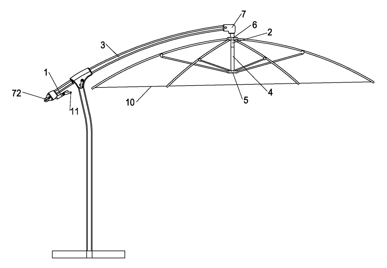
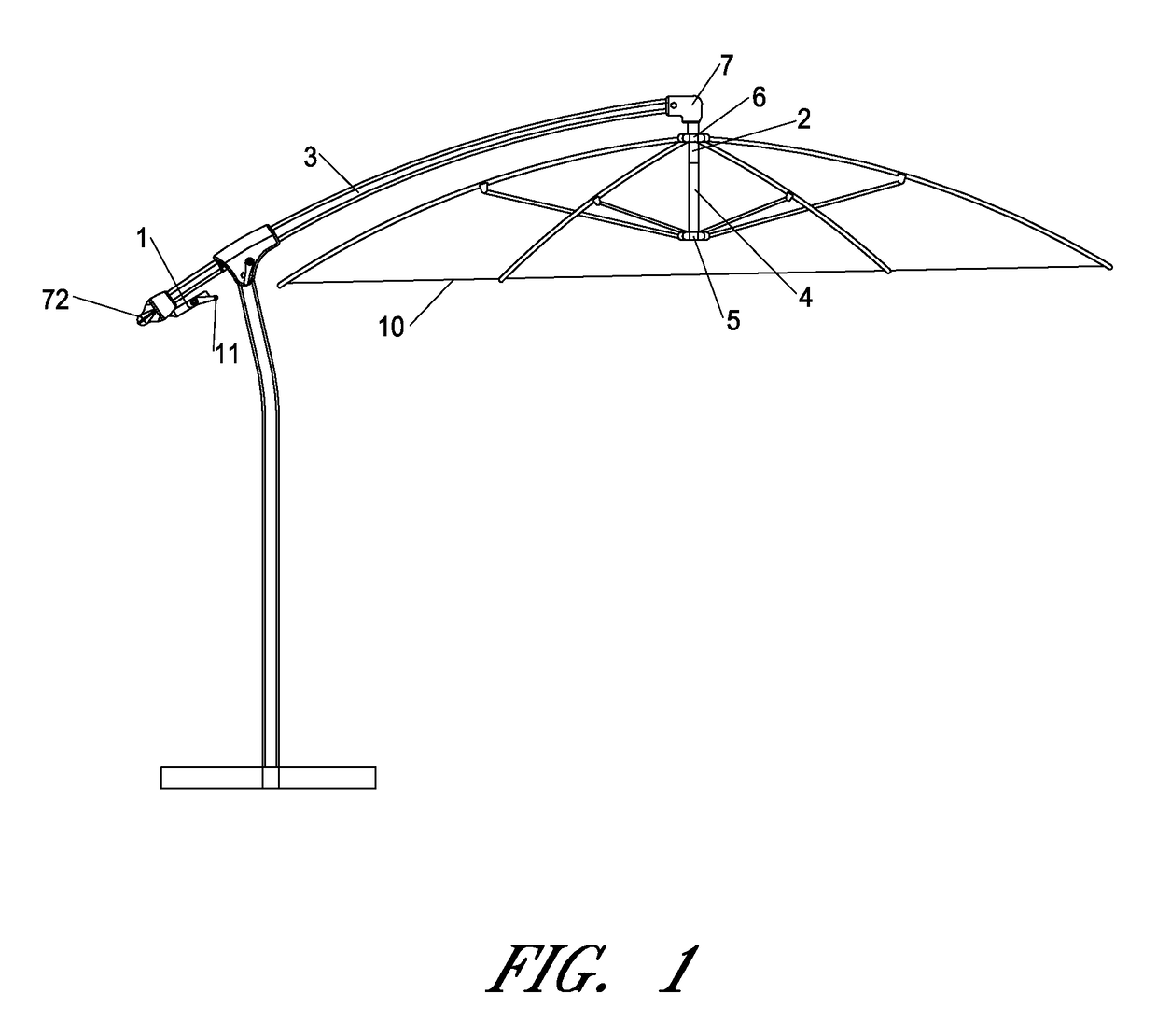
[0049]In order to have a clearer understanding of the technical content of this umbrella canopy tilt mechanism, the following embodiments are specially cited and described in detail. The same reference numerals are used for the same parts.

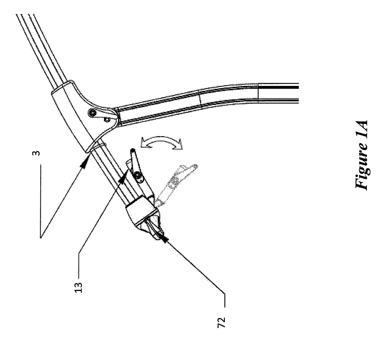
[0050]With reference to FIGS. 1-5, the canopy tilt mechanism of this invention includes a crank mechanism 1 and an automatic bending mechanism 2; the crank mechanism 1 includes a crank 11 and a rope 12 (e.g., cord, cable); the crank 11 is swivel-mounted on one end of the curved cantilever 3 of a sunshade umbrella; the automatic bending mechanism 2 is installed in the shaft 4 of the sunshade umbrella; one end of the rope 12 is connected to the crank 11, the other end of the rope 12 extends along the curved cantilever 3 to reach the other end of the curved cantilever 3 and rope 12 then passes (e.g., extending) through the shaft 4 and through the automatic bending mechanism 2 to connect to the lower runner 5 of the sunshade umbrella; the lower runner ...


PUM


Abstract

In some embodiments, an umbrella canopy tilt mechanism is provided that can include a crank mechanism and an automatic bending mechanism. The crank mechanism includes a crank and a rope. The crank is configured to be swivel-mounted on one end of the curved cantilever of a sunshade umbrella. The automatic bending mechanism is configured to be installed in a shaft of the sunshade umbrella. One end of the rope is configured to connect to the crank. The other end of the rope is configured to extend along the curved cantilever to reach the other end of the curved cantilever. The rope is configured to extend through the shaft and automatic bending mechanism to connect to a lower runner. The lower runner is held and slides on the shaft. An upper runner is fixedly secured to the shaft. The umbrella canopy tilt mechanism can further be provided with a rotation mechanism.

Description

INCORPORATION BY REFERENCE TO ANY PRIORITY APPLICATIONS[0001]Any and all applications for which a foreign or domestic priority claim is identified in the Application Data Sheet as filed with the present application, including Chinese Patent Application No. 201220292694.7, are hereby incorporated by reference under 37 CFR 1.57.BACKGROUND[0002]Field of the Invention[0003]This application involves the technical aspects of an umbrella, especially the technical aspects of sunshade umbrellas; this application specifically refers to an umbrella with a canopy tilt mechanism in some embodiments.[0004]Description of the Related Art[0005]In the common cantilever umbrellas, the opening / closing of the canopy and angle adjustment are two independent mechanisms. In addition, they are located at different parts or portions of the umbrella in different product designs.[0006]One such example is a Chinese utility model patent (name of patent: Offset Umbrella with Tilt Adjustment, Patent Number: ZL2005...

Claims


Application Information

Patent Timeline
Patent Type & Authority Patents(United States)
IPC IPC(8): A45B17/00A45B23/00
CPCA45B17/00A45B23/00A45B2023/0037A45B2023/0081
Inventor MA
Owner OLIVER JOEN AN MA
Learn More