
Achromatic optical-dispersion corrected gradient refractive index optical-element

a technology of optical components and gradients, applied in the field of optical dispersion correction of refractive gradient index (grin) optic design and manufacture, can solve problems such as chromatic aberration and unsatisfactory wavelength dependent focal shifts

Active Publication Date: 2017-05-09
VADIENT OPTICS
View PDF24 Cites 0 Cited by
  • Summary
  • Abstract
  • Description
  • Claims
  • Application Information

AI Technical Summary

Benefits of technology

This patent is about a method of making optical elements by using nanocomposite inks. These inks have nanofillers dispersed in a cured organic-matrix. The patent describes how by making the two inks in a specific way, they can create optical-dispersion gradients that correct chromatic aberration. This results in better quality optical elements.

Problems solved by technology

For imaging optics, optical-dispersion causes undesirable wavelength dependent focal shift, called chromatic aberration.

Method used


Image

  • Achromatic optical-dispersion corrected gradient refractive index optical-element
  • Achromatic optical-dispersion corrected gradient refractive index optical-element
  • Achromatic optical-dispersion corrected gradient refractive index optical-element

Examples


Embodiment Construction

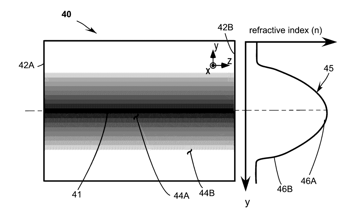
[0035]Referring now to the drawings, wherein like components are designated by like reference numerals. Drawings are characterized by cartesian (mutually perpendicular) axes x, y, and, z, although anyone skilled in the art can transform the axis to other coordinates or topologies. When referring to an optical-element, the z-axis refers generally to the direction of light propagation, and x and y being transverse axes. Methods of manufacture and optical-elements are described further herein below.

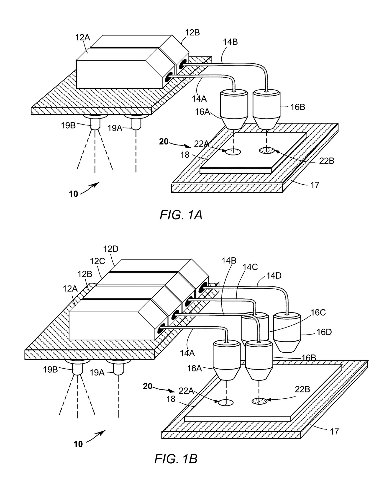
[0036]FIG. 1A schematically illustrates an ink jet printing apparatus 10 for manufacture of optical-elements in accordance with the present disclosure. Printing apparatus 10 is simplified for explanatory purposes. Those skilled in the art will generally recognize the ink-jet printing approach, see Richard Chartoff et al., “Functionally Graded Polymer Matrix Nano-Composites by Solid Freeform Fabrication,” presented at the 2003 Solid Freeform (SFF) symposium and Richard Chartoff et al., “Polym...


PUM

PropertyMeasurementUnit
optical-dispersion aaaaaaaaaa
optical-dispersionaaaaaaaaaa
opticalaaaaaaaaaa

Abstract

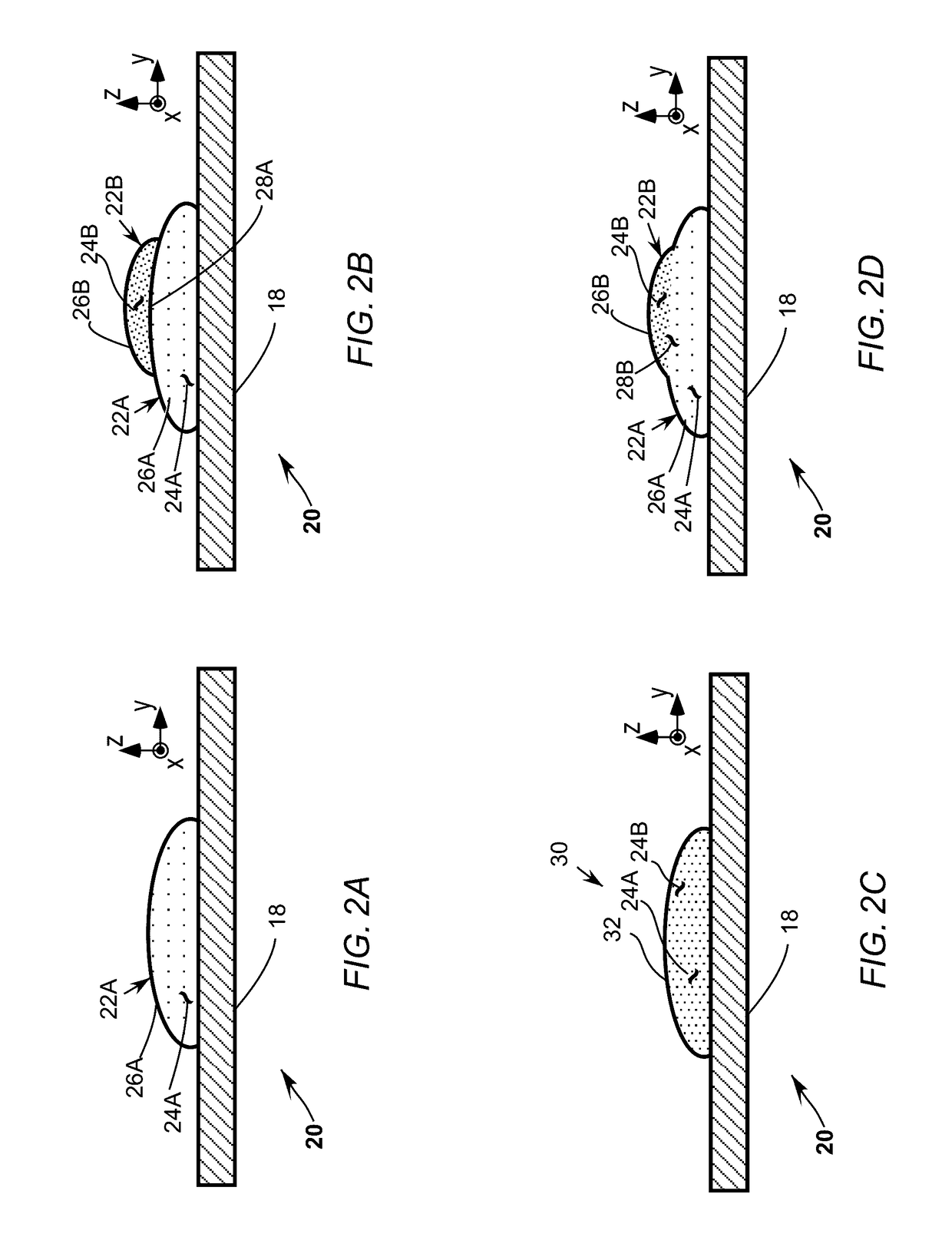
An optical-dispersion corrected optical-element, the optical-element comprising a first nanocomposite-ink, the first nanocomposite-ink comprising nanofillers dispersed in a cured organic-matrix, a second nanocomposite-ink, the second nanocomposite-ink comprising the nanofillers dispersed in a the cured organic-matrix, optical-dispersion of the second nanocomposite-ink different than optical-dispersion of the first nanocomposite-ink, wherein the distribution of the first nanocomposite-ink and the second nanocomposite-ink result in optical-dispersion refractive-gradients, where the refractive-gradients correct chromatic aberration.

Description

REFERENCE TO RELATED PATENTS[0001]This application is a continuation-in-part of U.S. patent application Ser. No. 14 / 293,574 filed Jun. 2, 2014 and this application also claims the benefit of U.S. Provisional Patent Application No. 62 / 013,500 filed Aug. 8, 2014.TECHNICAL FIELD OF THE DISCLOSURE[0002]The present disclosure relates in general to correcting optical chromatic aberration caused by optical-dispersion in media. The disclosure relates in particular to optical-dispersion corrected refractive-gradient index (GRIN) optic design and manufacture using printing technology.DISCUSSION OF BACKGROUND ART[0003]Optical-dispersion is a well-known optical phenomenon which refers to wavelength dependency of refractive index in media. For applications such as spectroscopy, optical-dispersion can be desirable to cause wavelength separation. For imaging optics, optical-dispersion causes undesirable wavelength dependent focal shift, called chromatic aberration. A variety of solutions to reduce...

Claims


Application Information

Patent Timeline
Patent Type & Authority Patents(United States)
IPC IPC(8): G02B13/14C09D11/38G02B3/00
CPCC09D11/38G02B3/0087G02B13/14G02B13/143B29D11/00355G02B13/146G02B27/0025G02B2207/101
Inventor WILLIAMS, GEORGE
Owner VADIENT OPTICS
Learn More