

Optical element and optical apparatus
a technology applied in the field of optical elements and optical apparatuses, can solve the problems of not providing a structure configured to correct the chromatic aberration of an optical system including a plurality of dioptric optical elements, and achieve the effect of correcting the chromatic aberration of an optical system
- Summary
- Abstract
- Description
- Claims
- Application Information
AI Technical Summary
Benefits of technology
Problems solved by technology
Method used
Image

Examples
first embodiment
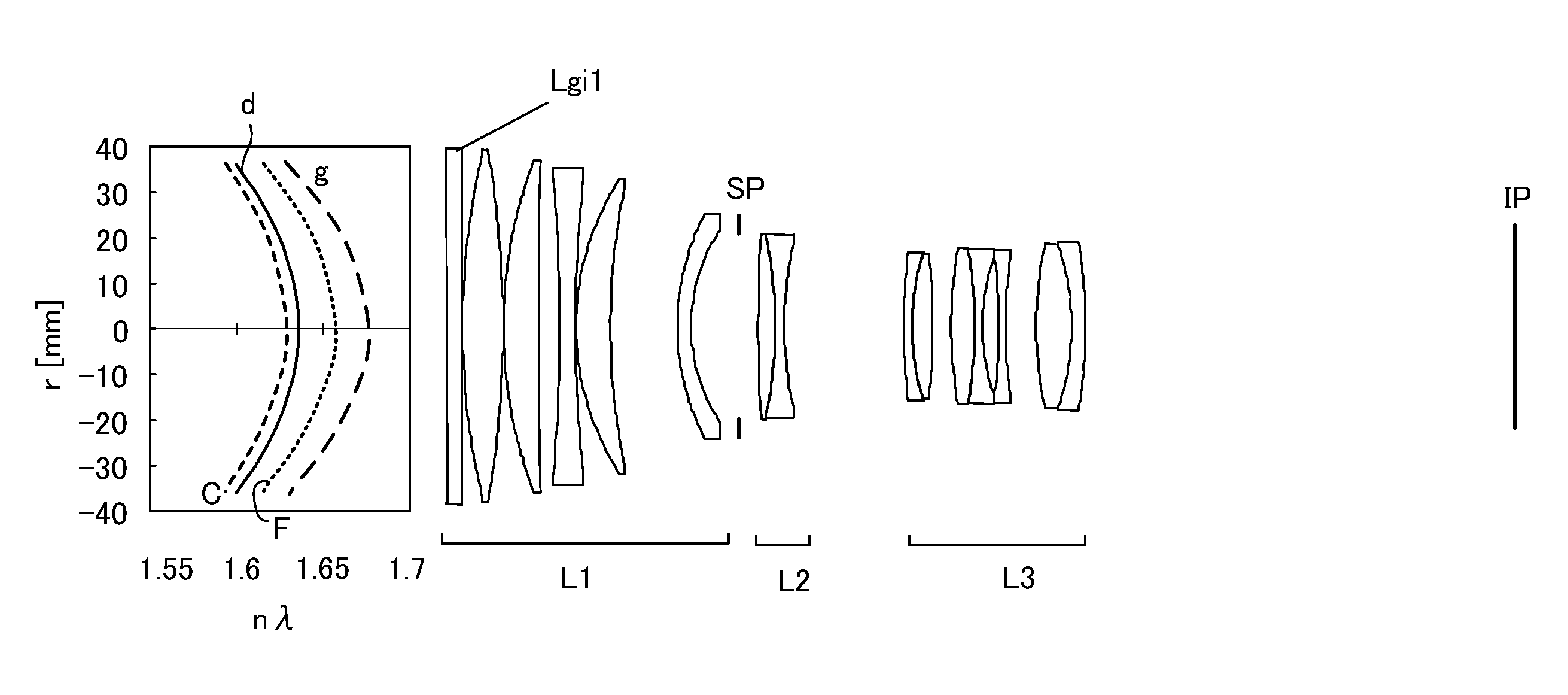
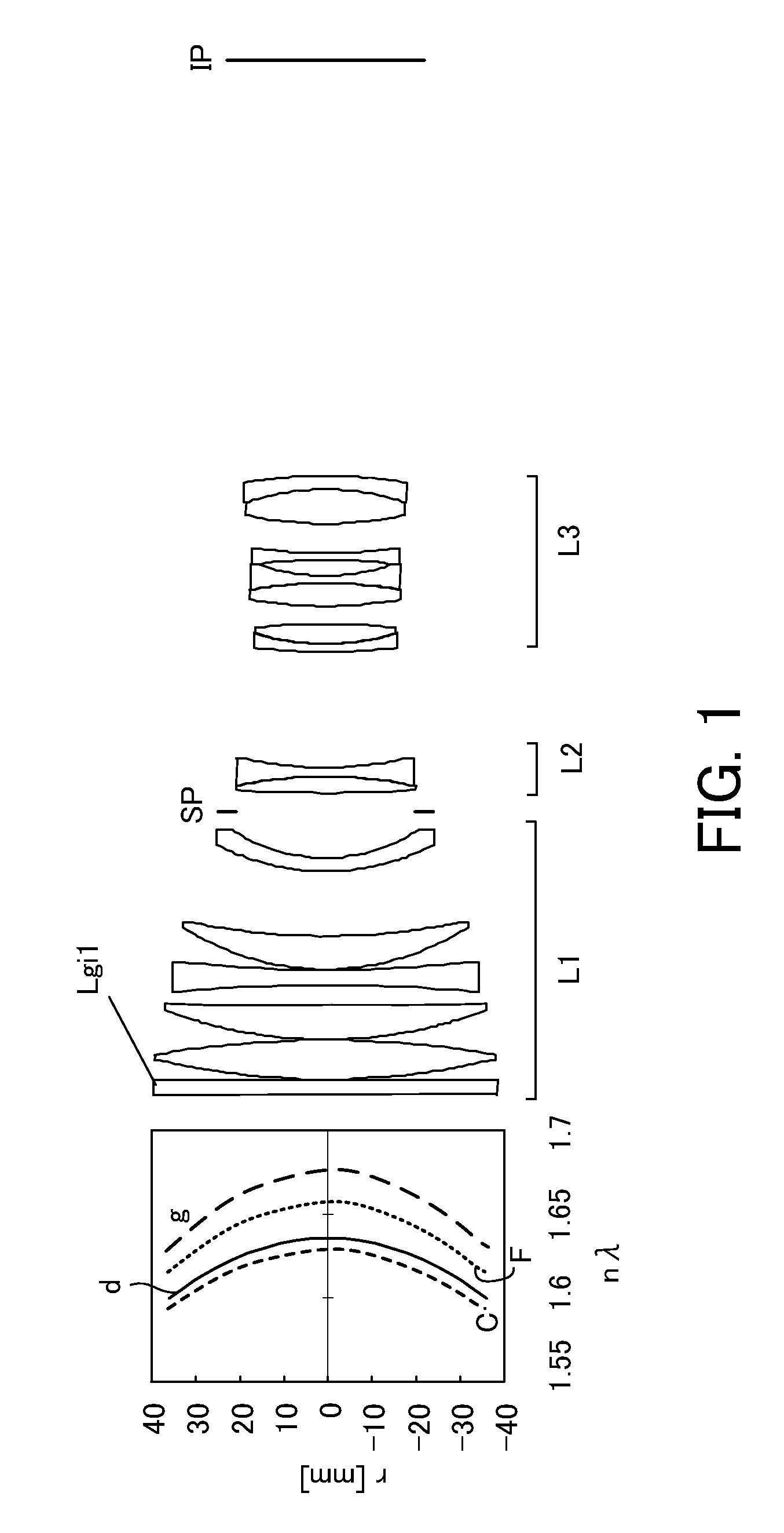
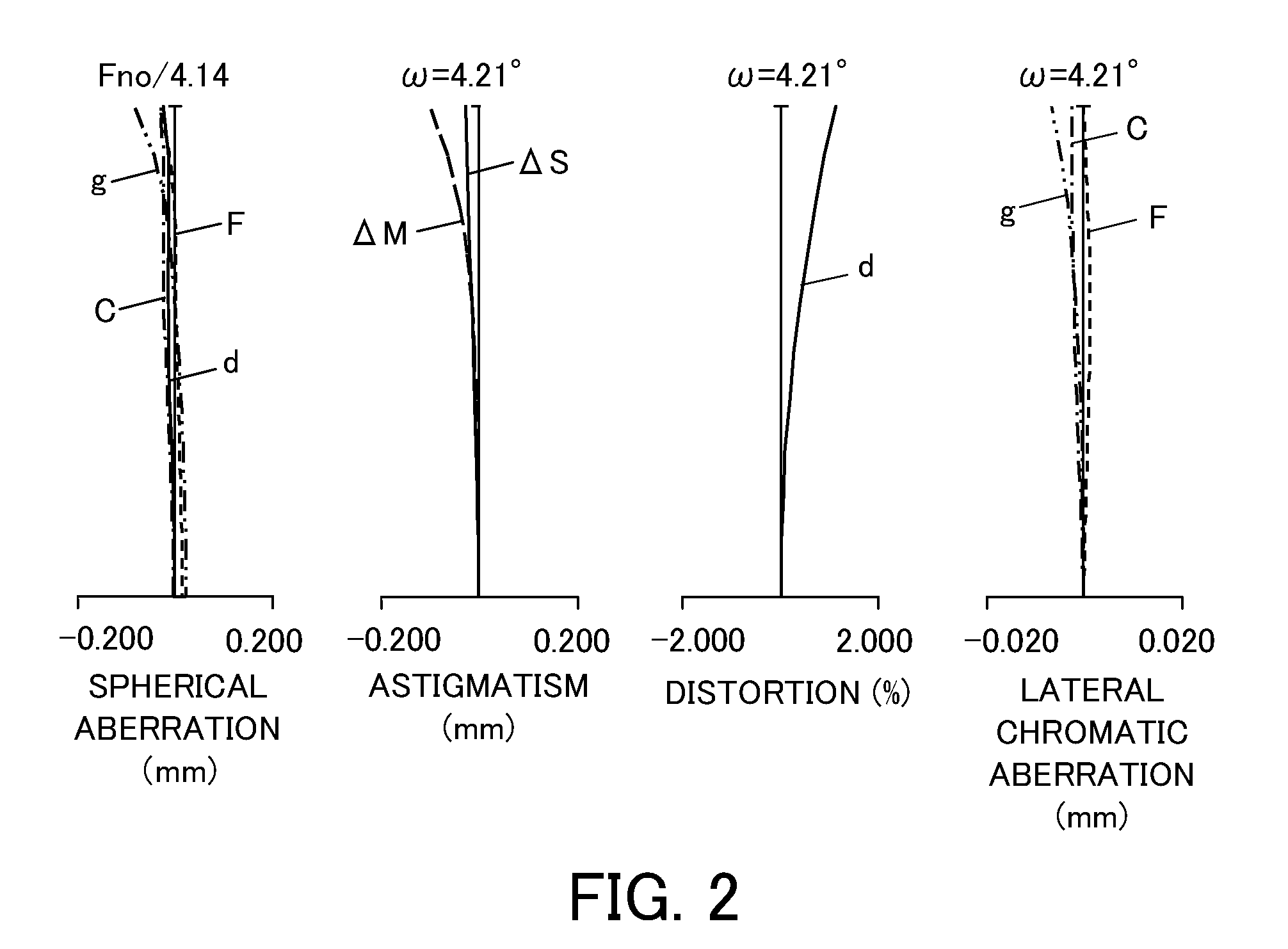
[0062]An optical system according to the first embodiment is a telephoto lens having a focal length of 294 mm and a telephoto ratio of 0.78. The optical system according to the first embodiment illustrated in FIG. 1 includes a first lens unit L1 of a positive refractive power which is fixed during focusing, a second lens unit L2 which has a negative refractive power and is configured to move in the optical axis direction during focusing, and a third lens unit L3 of a negative refractive power which is fixed during focusing.
[0063]The first embodiment uses a radial gradient-index optical element Lgi1 that includes resins 1 and 2 characteristics described in Table 1. The resin 1 is UV curable resin, and resin 2 is fluorine-based resin. This gradient-index optical element has a volume ratio of 100% of resin 1 on the optical axis and a volume ratio of 100% of resin 2 at r=36 mm. The refractive index of the resin 1 is higher than that of the resin 2, and the refractive index reduces from ...
second embodiment
[0066]An optical system of a second embodiment is a telephoto lens that has the same specification and the same unit structure as that of the first embodiment, and FIG. 3 is a sectional view of the optical system.
[0067]The second embodiment uses a radial gradient-index optical element Lgi1 that includes ITO particles dispersed fluorine resin 3 having characteristics described in Table 1. This gradient-index optical element has a volume ratio of 0% of the ITO particles to the resin 3 on the optical axis and its volume ratio of 5% at r=36 mm. The refractive index increases from the optical axis to the effective beam diameter, and the refractive power of the refractive index distribution is negative. Making a difference between Δθgd(0) of the medium on the optical axis and the Δθgd(re) of the medium on the effective beam diameter enhances Δθgdgi(r)(Δθgdgi(r)<0).
[0068]The gradient-index optical element that can correct the chromatic aberrations for four wavelengths is realized by using ...
third embodiment
[0070]An optical system of a third embodiment is a normal lens that has a focal length of 51.5 mm, and FIG. 5 is a sectional view of the optical system.
[0071]The third embodiment uses two gradient-index optical elements. A gradient-index optical element Lgi1 is placed at the first lens unit L1 and another gradient-index optical element Lgi2 is placed at f the second lens unit L2. Lgi1 has a volume ratio of 100% of the resin 1 on the optical axis and a volume ratio of 100% of resin 4 at r=15 mm. The resin 4 is fluorine-based resin that has a characteristic in Table 1. The refractive index of the resin 1 is larger than that of the resin 4, and reduces from the optical axis to the effective beam diameter. The refractive power of the gradient-index optical element is positive.
[0072]Lgi2 is a radial gradient-index optical element that includes the ITO particles dispersed in acrylic resin 5, and has a volume ratio of 0% of the ITO particles to the acrylic resin 5 on the optical axis and a...
PUM
 Abstract
Description
Claims
Application Information