

Hybrid refractive gradient-index optics for time-of-fly sensors
a technology of time-of-fly and gradient index, applied in the field of optics, can solve the problems of insufficient reliability or accuracy of approaches to support more advanced features, and it is difficult to integrate such time-of-fly techniques into portable digital electronics applications such as smart phones, and achieve the effect of less refractive aberration
- Summary
- Abstract
- Description
- Claims
- Application Information
AI Technical Summary
Benefits of technology
Problems solved by technology
Method used
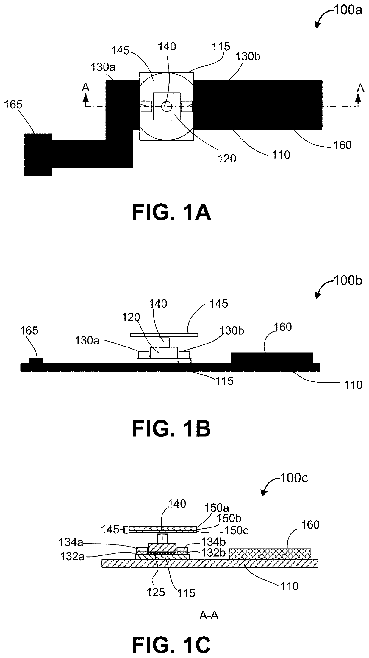
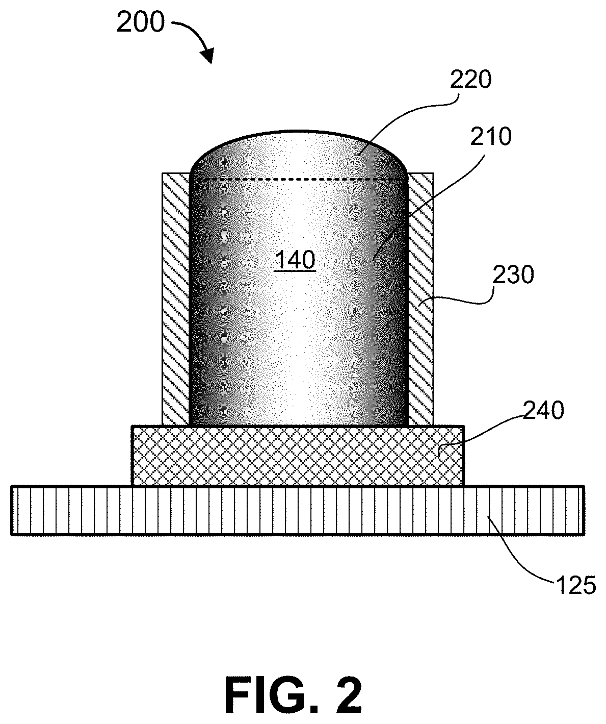
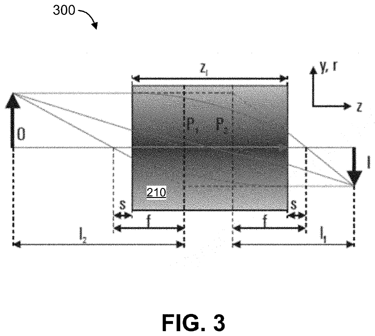
Image

Examples
Embodiment Construction
[0014]In the following description, numerous specific details are provided for a thorough understanding of the present invention. However, it should be appreciated by those of skill in the art that the present invention may be realized without one or more of these details. In other examples, features and techniques known in the art will not be described for purposes of brevity.
[0015]Increasingly, digital imaging is exploiting depth information to support various features. For example, in three-dimensional computer graphics, depth maps are used to indicates information relating to the distance of the surfaces of scene objects from a viewpoint. Similarly, in digital photography, depth mapping, and the like, can be used to support three-dimensional image capture features, enhanced auto-focusing features, and other features. Various techniques are generally known for acquiring such depth information, such as so-called “time-of-fly” (TOF) techniques. TOF techniques generally measure a di...
PUM
| Property | Measurement | Unit |
|---|---|---|
| TOF imaging | aaaaa | aaaaa |
| focal length | aaaaa | aaaaa |
| TOF | aaaaa | aaaaa |
Abstract
Description
Claims
Application Information