Optical system for a laser therapy instrument

a laser therapy and optical system technology, applied in the field of optical system for laser therapy instruments, can solve the problems of ineffective purchase cost, insufficient instruments available, time-consuming setting up of several instruments for examining and treating the same patient eye, etc., and achieves the effect of avoiding axial resolution loss occurring upon switching between the two configurations, maximum useful aperture, and large apertur

Active Publication Date: 2014-04-24
CARL ZEISS MEDITEC AG
View PDF9 Cites 1 Cited by
  • Summary
  • Abstract
  • Description
  • Claims
  • Application Information

AI Technical Summary

Benefits of technology

[0025]Axial resolution losses occurring upon switching between the two configurations are avoided in that the optical design of the expanders is coupled to the configuration change, for example, in that two expanders in the therapeutic laser beam path are exchanged against one another. Both expanders have beam path lengths which are independent of one another and are inserted into the beam path alternatingly depending on the configuration selected by the user.
[0026]Because of the varied depths of the focus positions in the anterior segment of the eye, there is, for each focus position, a maximum useful aperture, which is limited because of the free optical diameter of the optical focussing system and because of the ana

Problems solved by technology

The possibilities known in prior art of medical treatment of the cornea lying at the periphery of the eye on the one hand, and of the crystalline lens lying within the eye on the other, have the disadvantage that the instruments available satisfy the requirements of their respective special purpose only, which means that they differ, especially with regard to the focus position in the eye, the aperture and the size of the focus volume, to such an extent that they are designed and suitably either for therapy of the cornea alone or for therapy of the crystalline lens alone.
This requires extensive instrumentation that is ineffective both with regard to purchase costs and because several separate instruments are used below their capacity most of the time.
In addition, setting up the several instruments separately for exam

Method used


Image

  • Optical system for a laser therapy instrument
  • Optical system for a laser therapy instrument
  • Optical system for a laser therapy instrument

Examples


Embodiment Construction

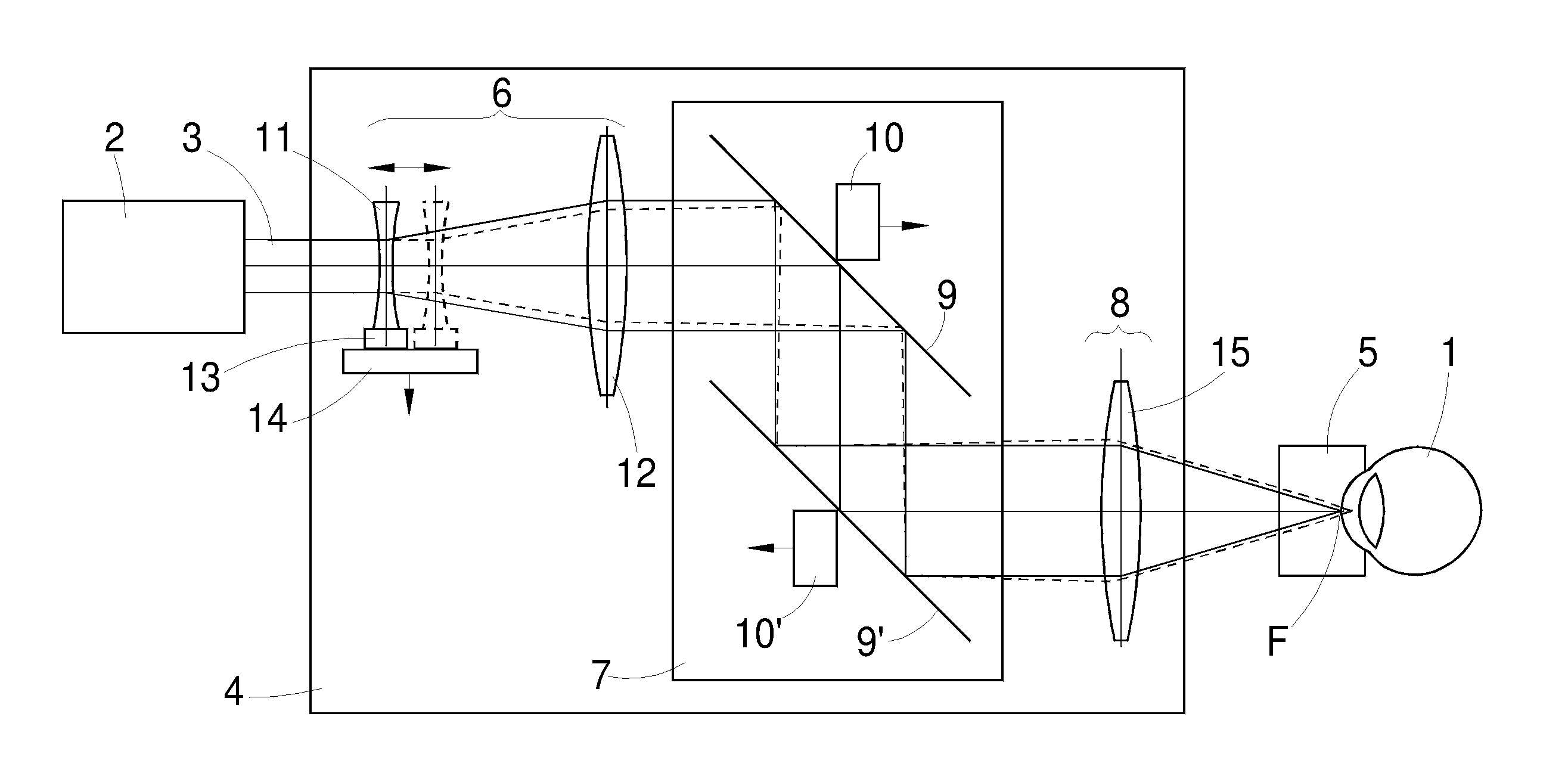
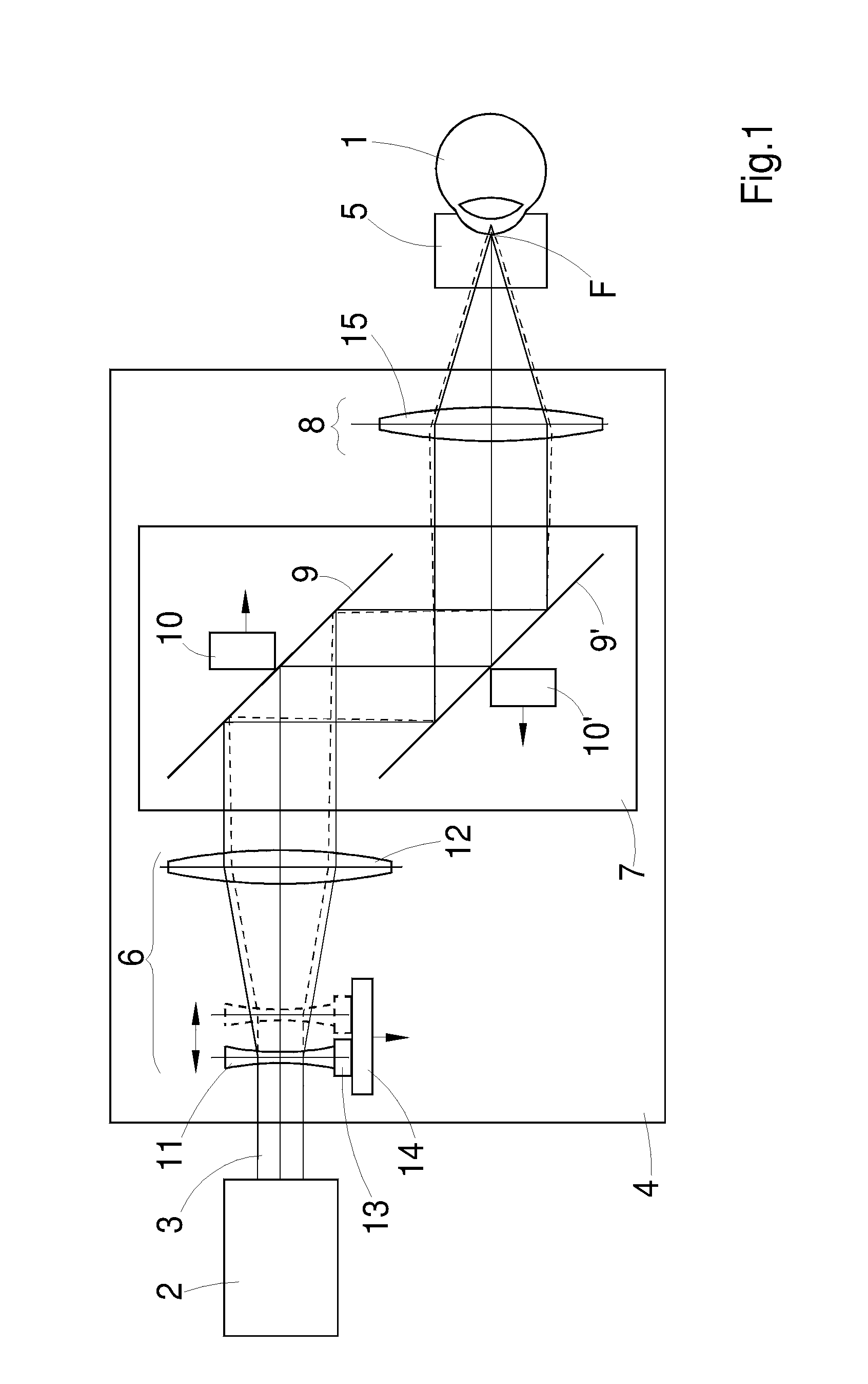
[0033]The optical system shown in FIG. 1, for an instrument for therapy of a human eye 1 represents the present state of prior art. It comprises a radiation source 2, which delivers a beam 3 of pulsed laser radiation in the femtosecond range, and a scanning device 4, with which the beam 3 is focussed onto selected positions within the region of the cornea. On the cornea there is a contact glass 5 that has a concave contact surface and suppresses movements of the eye 1 during treatment.

[0034]The radiation source 2 is designed, e.g., to deliver laser radiation in the wavelength range around 1040 nm with a pulse width in the region of about 200 fs.

[0035]The scanning device 4 has, in the direction of the beam 3 originating from the radiation source 2, an optical assembly 6, behind which in the beam direction, there follows a deflecting device 7. According to given control signals, the deflecting device 7 deflects the beam 3 exiting the optical assembly 6 in a lateral direction, i.e. in ...


PUM


Abstract

An optical system for a laser therapy instrument for the application of laser radiation on and in the eye, includes a femtosecond laser, an objective. The objective or at least one lens or lens group of the objective is shiftable in the direction of the optical axis being intended for shifting of the focus position from the region of the cornea to the region of the crystalline lens and vice versa. The optical system may include at least two optical assemblies designed for the axial variation of the focus of the therapeutic laser radiation, with the focus variation range Δz differing between the individual assemblies and a changing device, designed for the insertion of any one of these assemblies into the therapeutic laser beam path at a time.

Description

RELATED APPLICATIONS[0001]The present application is a National Phase entry of PCT Application No. PCT / EP2012 / 054743, filed Mar. 19, 2012, which claims priority from DE Application No. 10 2011 075 799.6, filed May 13, 2011, and U.S. Patent Application No. 61 / 485,995, filed May 13, 2011, which applications are incorporated by reference herein in their entirety.FIELD OF THE INVENTION[0002]The present invention relates to an optical system for a laser therapy instrument for the application of laser radiation on and in the eye, suited particularly for laser surgery of the cornea and / or of the crystalline lens.BACKGROUND[0003]Laser therapy instruments are used, e.g., for correcting an ametropia of the human eye by a laser-surgical operation of the cornea. For this purpose, a lid is formed on the outer surface of the cornea, which lid is attached along one edge and is therefore known as a flap, and the thickness of which is substantially smaller then the thickness of the cornea. For corre...

Claims


Application Information

Patent Timeline
IPC IPC(8): A61F9/008
CPCA61F9/008A61F9/00825A61F9/0084A61F2009/0087A61F2009/00872A61F2009/00874
Inventor STOBRAWA, GREGORBISCHOFF, MARK
Owner CARL ZEISS MEDITEC AG
Why Eureka
Try Eureka