Wearable display apparatus having a light guide element that guides light from a display element and light from an outside

a technology of light guide elements and display elements, which is applied in the field of wearable display devices, can solve the problems of user isolation from a real surrounding environment, affecting the resolution of virtual image information, and not being desirable for a portable electronic devi

Active Publication Date: 2020-05-14
SAMSUNG ELECTRONICS CO LTD
View PDF0 Cites 1 Cited by
  • Summary
  • Abstract
  • Description
  • Claims
  • Application Information

AI Technical Summary

Benefits of technology

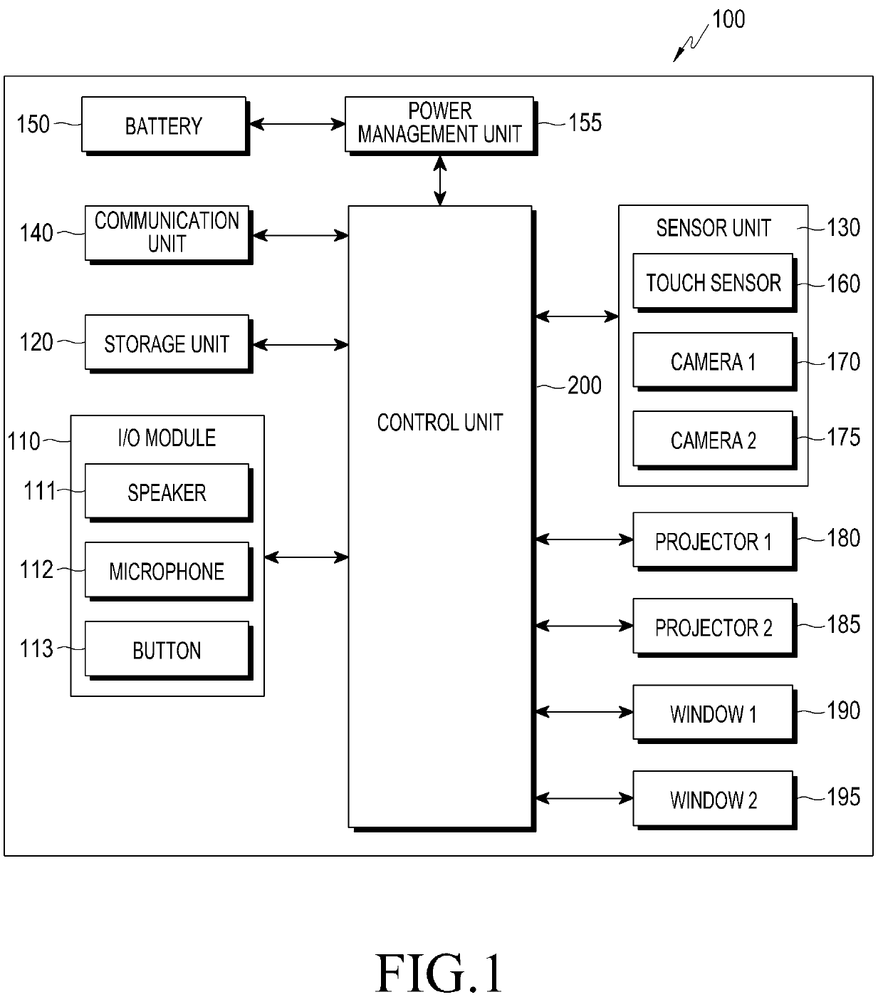
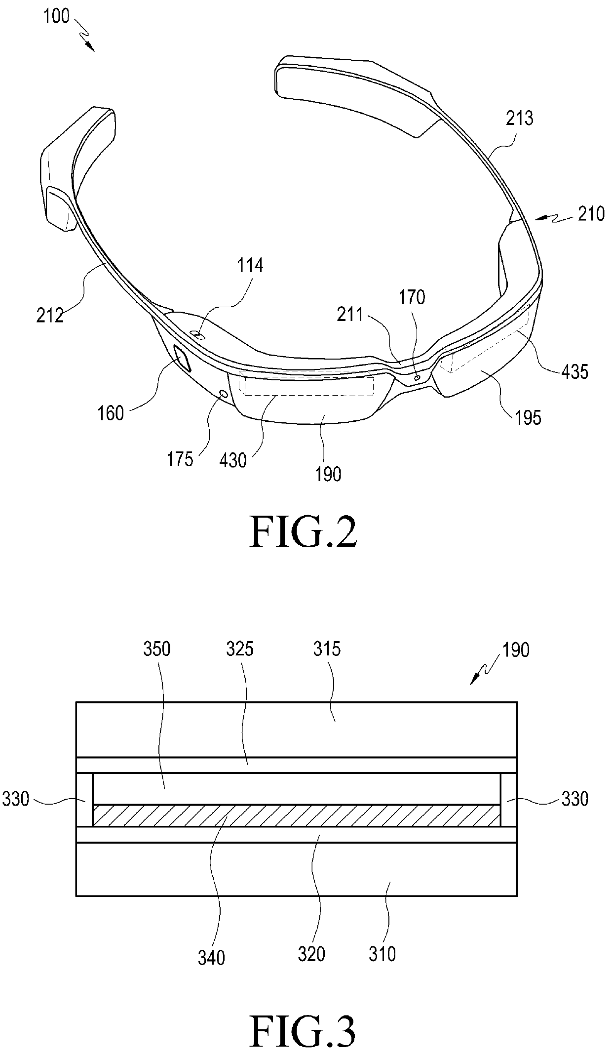
[0007]Aspects of one or more exemplary embodiments provide a compact and light wearable display device in which an aberration by a manufacturing tolerance occurs less often.
[0031]The wearable display device may further include a transparent cover glass on a surface of the display element facing the light guide element, to protect the surface of the display element.

Problems solved by technology

Since an electronic device of this type is inconvenient to carry and use, the electronic device may mainly be used in a limited environment, for example, indoors.
The video see-through type has a problem in that since the user is to recognize surroundings based on only the image obtained through the camera, the user may be isolated from a real surrounding environment.
However, the optical see-through type has a problem in that the resolution of the virtual image information may be considerably changed depending on a luminous intensity.
However, this is not desirable for a portable electronic device since the consumption of power increases at the high resolution.
Additionally, the related art optical see-through type display devices have problems in that they are thick, are poor in image quality due to occurrence of aberrations, have a complicated manufacturing process, are heavy, and so on.

Method used


Image

  • Wearable display apparatus having a light guide element that guides light from a display element and light from an outside
  • Wearable display apparatus having a light guide element that guides light from a display element and light from an outside
  • Wearable display apparatus having a light guide element that guides light from a display element and light from an outside

Examples


Embodiment Construction

[0068]The present disclosure may be variously changed and may have various exemplary embodiments. Exemplary embodiments exemplified in the drawings will be described in detail below. However, it should be understood that the present disclosure is not limited to these exemplary embodiments, but the present disclosure includes all modifications, equivalents, and alternatives within the spirit and the scope of the present disclosure.

[0069]Although the terms including an ordinal number such as first, second, etc., can be used for describing various elements, the structural elements are not restricted by the terms. The terms are only used to distinguish one element from another element. For example, without departing from the scope of the present disclosure, a first structural element may be named a second structural element. Similarly, the second structural element also may be named the first structural element. As used herein, the term “and / or” includes any and all combinations of one ...


PUM

PropertyMeasurementUnit
angleaaaaaaaaaa
distanceaaaaaaaaaa
angleaaaaaaaaaa

Abstract

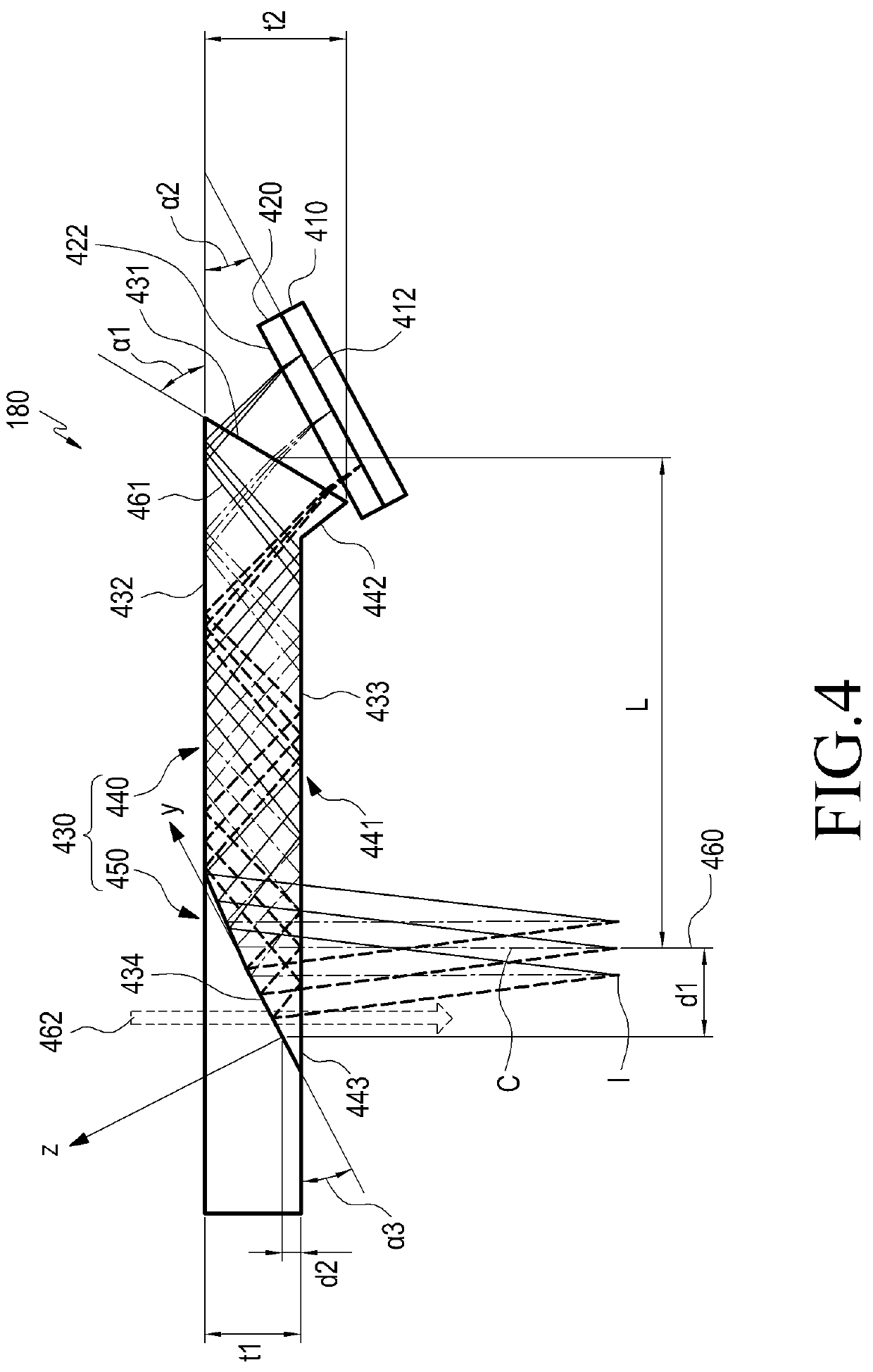
Provided are a wearable display device and a light guide element thereof, the display device including: a display element configured to project a first light forming a virtual image; and a light guide element configured to guide the first light from the display element and a second light input from outside of the wearable display device to a predetermined position. The light guide element includes: a first optical surface facing the display element; a second optical surface and a third optical surface configured to reflect the first light input through the first optical surface; and a fourth optical surface configured to reflect the reflected first light to the predetermined position. The first to third optical surfaces are flat surfaces, and the fourth optical surface is a rotationally asymmetric reflective surface.

Description

CROSS-REFERENCE TO RELATED APPLICATIONS[0001]This application is a Continuation Application of U.S. application Ser. No. 14 / 593,634, filed Jan. 9, 2015, which claims priority from Korean Patent Application Serial No. 10-2014-0002899, filed on Jan. 9, 2014 in the Korean Intellectual Property Office, and from Korean Application Serial No. 10-2014-0177758, filed on Dec. 10, 2014 in the Korean Intellectual Property Office, the entire contents of which are hereby incorporated by reference.BACKGROUND1. Field[0002]Apparatuses and methods consistent with exemplary embodiments relate to a wearable display device.2. Description of the Related Art[0003]Some commercially available body-wearable display devices may include an input / output (I / O) device configured to be worn on a part of a body, and a main circuit device or a battery configured as a separate module type. The circuit device or the battery configured as the separated module type may be connected to the I / O device through a wire. Sin...

Claims


Application Information

Patent Timeline
Patent Type & Authority Applications(United States)
IPC IPC(8): G02B27/01G06F3/01G06F3/0484G02B6/00
CPCG02B2027/014G02B2027/0147G02B2027/011G02B2027/0178G06K9/00006G02B27/0101G02B6/00G02B27/0172G06F3/013G02B2027/0118G06F3/04842G02B2027/0138G06V40/12
Inventor BAE, JAE-CHEOLCHOI, MYONG-JOKOH, JUN-HOKIM, CHANG-HANKIM, HYUN-JUNG
Owner SAMSUNG ELECTRONICS CO LTD
Why Eureka
Try Eureka