
Hybrid grin diffractive optics

a technology of diffractive optics and hybrid grin, applied in the field of hybrid grin diffractive optics, can solve the problems of affecting the final product, imposing additional size, weight, cost, manufacturing complexity, etc., and less able to correct for chromatic aberration, and imposing weight and weigh

Active Publication Date: 2016-10-11
RAYTHEON CO
View PDF18 Cites 0 Cited by
  • Summary
  • Abstract
  • Description
  • Claims
  • Application Information

AI Technical Summary

Problems solved by technology

With each additional optical element added to an imaging system, additional size, weight, cost, and manufacturing complexity are imposed on the final end product.
Typical diffractive optical elements have their own sets of limitations that do not always replace the functionality provided by their refractive counterparts.
While typical diffractive elements fashioned from homogeneous materials can be utilized for the correction of certain field aberrations, such as astigmatism, field curvature, and coma, they are less able to correct for chromatic aberrations due to the strong wavelength dispersion properties of most diffractive optical components.

Method used


Image

  • Hybrid grin diffractive optics
  • Hybrid grin diffractive optics
  • Hybrid grin diffractive optics

Examples


Embodiment Construction

[0033]Gradient index (GRIN) optical components are fashioned from bulk materials that have a smooth and controlled variation of refractive index over distance within the material. When tracing the path of an optical ray traveling through a GRIN material, the path of that optical ray is bent most strongly when the ray is perpendicular to an optical index gradient, and is not bent when traveling a path parallel to an index gradient. The refractive index profile of GRIN materials can be designed to vary in one, two or three separate dimensions. Three categories of GRIN materials of particular note include axial GRIN materials, spherical GRIN materials, and radial GRIN materials.

[0034]As depicted in FIG. 3A, axial GRIN materials 300 have variation of refractive index in only a single dimension, along the optical axis. As stated above, when the index variation 302 of an axial GRIN material is parallel to the light's direction of propagation, the axial GRIN material provides no refractive...


PUM


Abstract

In one embodiment, an optical imaging system is disclosed incorporating at least two gradient refractive index optical elements of a plurality of gradient refractive index optical elements made from at least one bulk material having a gradient refractive index and at least one diffractive optical element of a plurality of diffractive optical elements integrated within at least one of the plurality of gradient refractive index optical elements. Various embodiments disclosed incorporate at least one diffractive optical element configured as a surface relief structure patterned on at least one surface of the at least one gradient refractive index optical element. The surface relief structure includes at least one of a diffraction grating structure, a diffractive lens structure, and a kinoform structure. The at least one bulk material includes at least one of a radial gradient refractive index, an axial gradient refractive index, and a spherical gradient refractive index.

Description

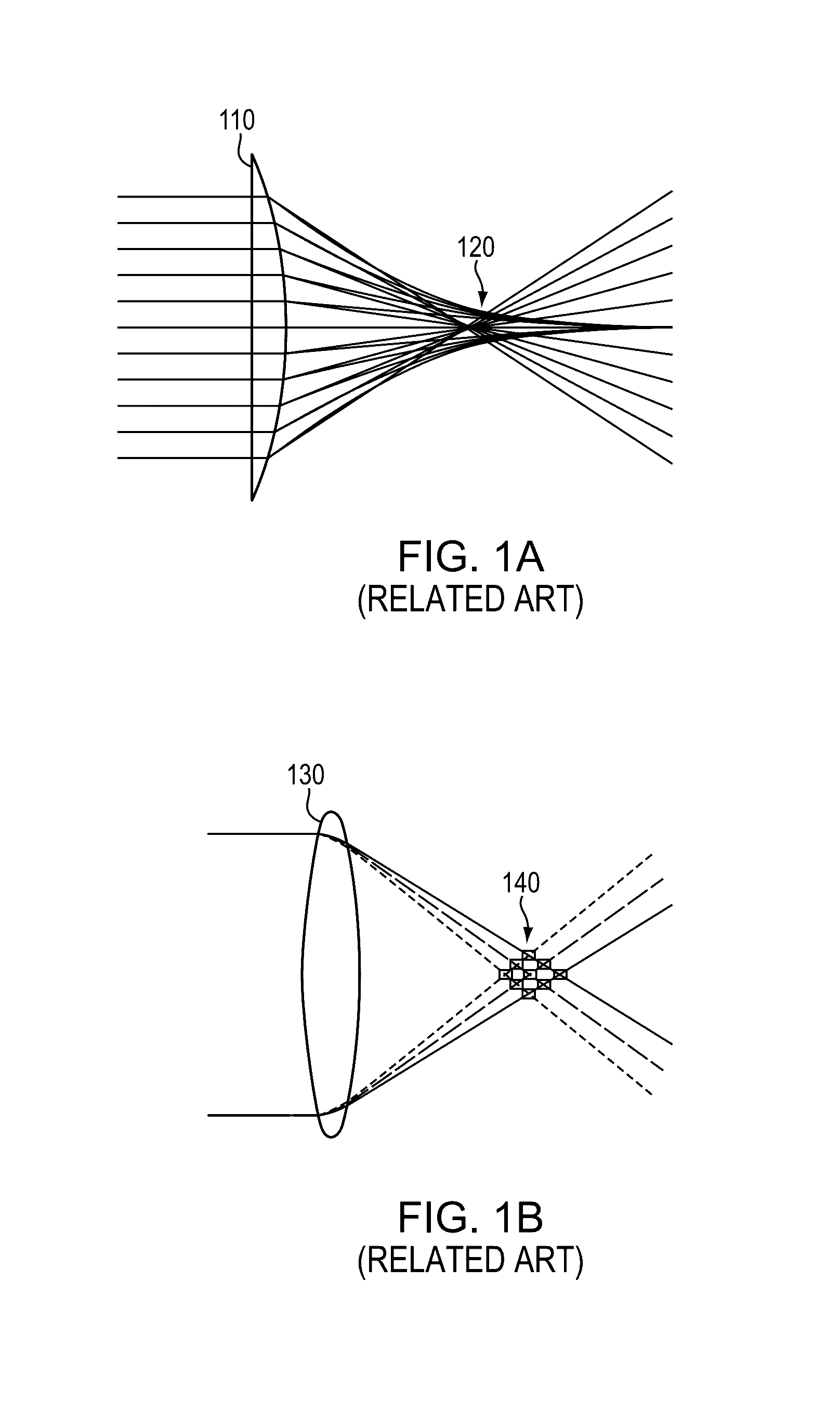
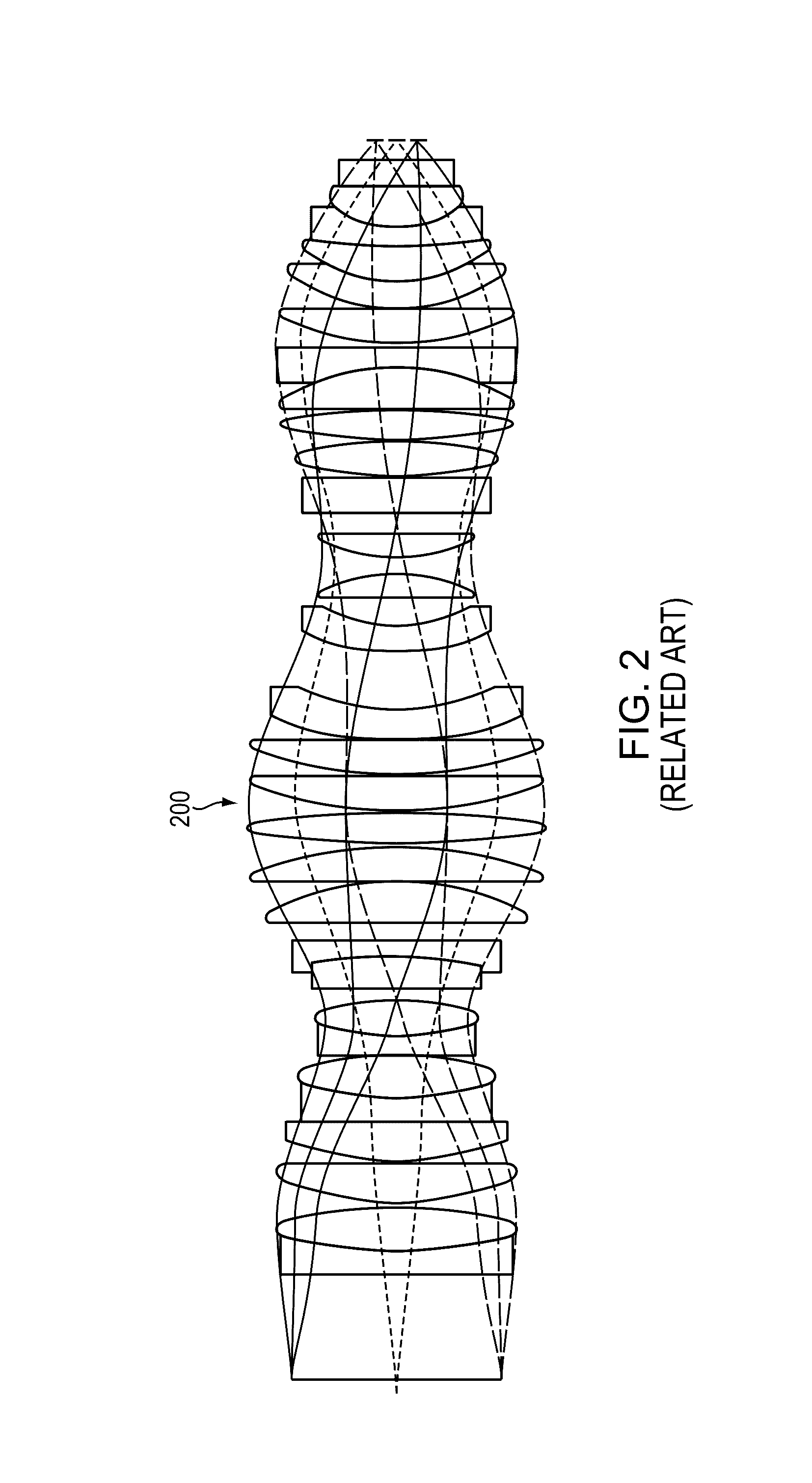
BACKGROUND[0001]Optical imaging systems have traditionally been created using either reflective or refractive optical elements. When refractive optical elements are used within imaging systems, these components often take the form of lenses with one or two curvature radii crafted within a homogeneous material. Use of refractive optical elements introduces various types of geometric and chromatic aberrations onto an optical image plane.[0002]FIG. 1A depicts a lens 110 made of a homogeneous material as well as the spherical aberration 120 produced when imaging an object positioned at infinity. Similarly, FIG. 1B depicts a lens 130 made of a homogeneous material as well as the chromatic aberration 140 produced when imaging an object at positioned at infinity for various wavelengths. Overcoming these aberrations, as well as others such as coma, astigmatism, field curvature and distortion, to produce an image of desired quality often requires the introduction of numerous optical elements...

Claims


Application Information

Patent Timeline
Patent Type & Authority Patents(United States)
IPC IPC(8): G02B3/00G02B3/04G02B27/42G02B5/18G02B3/02G02B25/00
CPCG02B5/1814G02B27/4211G02B27/4216G02B3/0087G02B3/04G02B3/00G02B3/02G02B25/001G02B2003/0093
Inventor CHIPPER, ROBERT B.
Owner RAYTHEON CO
Learn More