Surgical device

a surgical device and driver technology, applied in the field of surgical devices, can solve the problems of increasing increasing the number of cables, and complicated mechanical structure of the surgical device in which drivers are mounted to drive the cables, so as to increase the number of joints, increase the number of cables, and reduce the effect of backlash

Active Publication Date: 2017-05-16
SAMSUNG ELECTRONICS CO LTD
View PDF13 Cites 56 Cited by
  • Summary
  • Abstract
  • Description
  • Claims
  • Application Information

AI Technical Summary

Benefits of technology

[0006]When a joint part of a surgical device is driven by using a cable, if the number of joint parts is increased, the number of cables is increased proportionally, so that a mechanical structure of the surgical device in which drivers are mounted to drive the cables may be complicated. In the surgical device formed of a plurality of joints, movement of a cable to drive a last joint may affect movement of other joints. This problem increases as the number of joints is increased. As a distance between the surgical device and a driver arranged in an active arm increases, backlash may increase. In order to decrease the backlash, large tension is applied to a cable, and in this regard, if the cable is permanently deformed due to use for a long time, driving accuracy of the joint parts may deteriorate.

Problems solved by technology

When a joint part of a surgical device is driven by using a cable, if the number of joint parts is increased, the number of cables is increased proportionally, so that a mechanical structure of the surgical device in which drivers are mounted to drive the cables may be complicated.
This problem increases as the number of joints is increased.
As a distance between the surgical device and a driver arranged in an active arm increases, backlash may increase.
In order to decrease the backlash, large tension is applied to a cable, and in this regard, if the cable is permanently deformed due to use for a long time, driving accuracy of the joint parts may deteriorate.

Method used


Image

  • Surgical device
  • Surgical device
  • Surgical device

Examples


Embodiment Construction

[0041]Reference will now be made in detail to embodiments, examples of which are illustrated in the accompanying drawings, wherein like reference numerals refer to like elements throughout. In the drawings, like reference numerals in the drawings denote like elements, and the size of each component may be exaggerated for clarity. As used herein, the term “and / or” includes any and all combinations of one or more of the associated listed items.

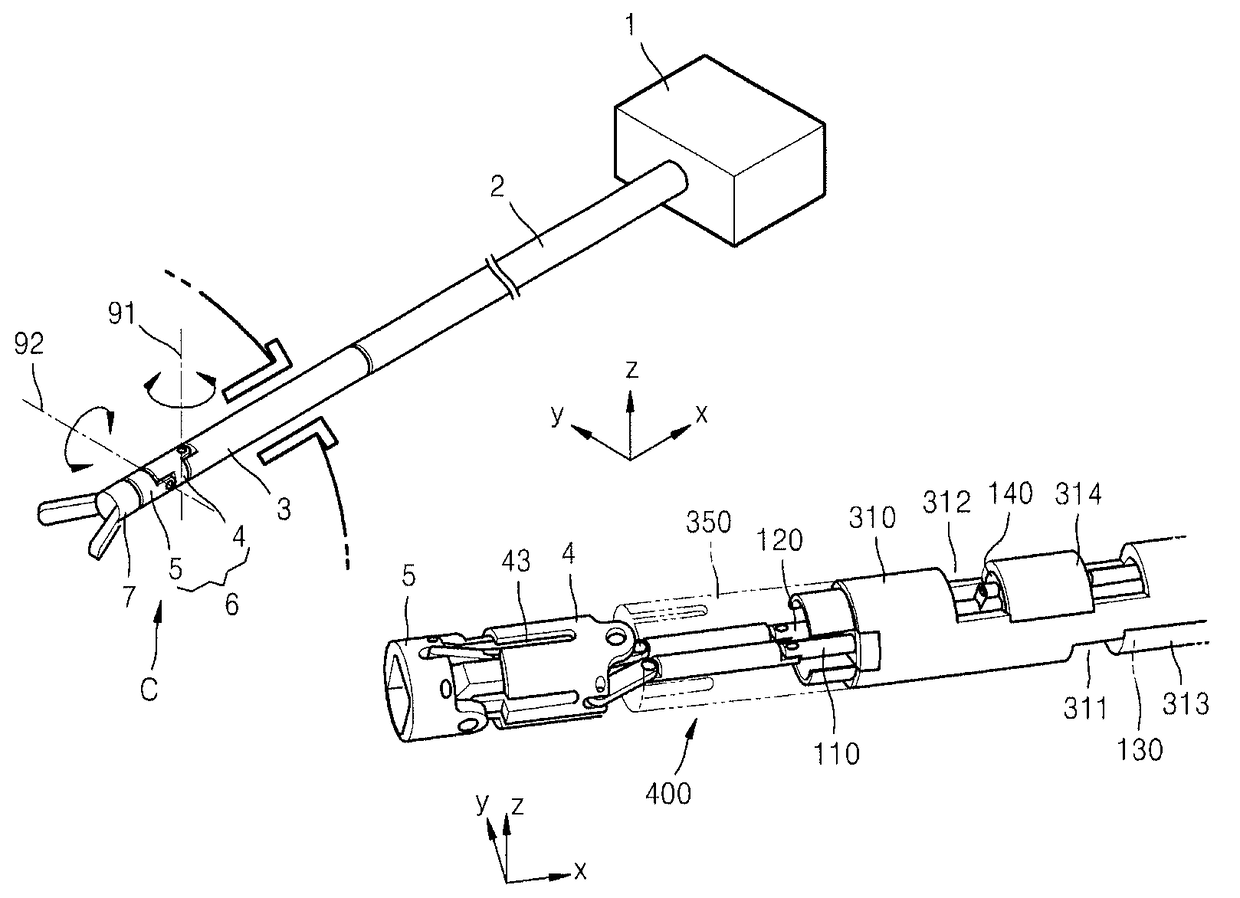
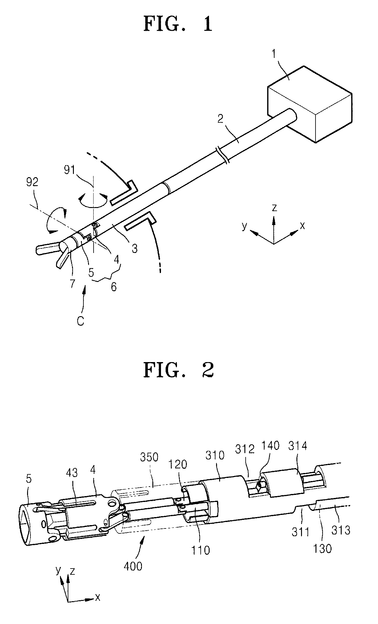
[0042]FIG. 1 is a perspective view of a surgical device according to an example embodiment of the present disclosure. Referring to FIG. 1, the surgical device includes a mounting part 1 to be mounted on a robot arm of a surgical robot (not shown), and an extension part 2 extending from the mounting part 1. The extension part 2 may have a thin and long bar shaped so as to be inserted into a human body, e.g., an abdominal cavity, a joint, or the like, in order to access an affected part. A joint driving part 3 and a joint part 6 are sequentially c...


PUM


Abstract

A surgical device, the surgical device including a mounting part mounted on a robot arm of a surgical robot; an extension part extending from the mounting part; a joint driving part that comprises a driving motor having a driving axis, that comprises a driving rod connected to the driving axis and reciprocating, and that is connected to an end of the extension part; and a joint part that is connected to the joint driving part, that is driven at one or more degrees of freedom by the driving rod, wherein the driving motor is connected to the driving axis with an elastic connection member.

Description

CROSS-REFERENCE TO RELATED APPLICATIONS[0001]This application claims the priority benefit of Korean Patent Application No. 10-2011-0054147, filed on Jun. 3, 2011, in the Korean Intellectual Property Office, the disclosure of which is incorporated herein in its entirety by reference.BACKGROUND[0002]1. Field[0003]The present disclosure relates to a surgical device that is mounted on a robot arm of a surgical robot, that is inserted into a human body, and that has at least one joint part.[0004]2. Description of the Related Art[0005]A surgical robot is a robot that performs a minimally invasive surgery by using a small surgical tool to insert into a human body. The surgical robot has a plurality of robot arms. A robot arm may include a passive arm that is manually operated during preparation before a surgical operation, and an active arm that is operated according to the motion of an operator during a surgical operation. A surgical device is mounted to the active arm so as to be inserte...

Claims


Application Information

Patent Timeline
Patent Type & Authority Patents(United States)
IPC IPC(8): A61B34/30
CPCA61B34/30A61B2034/302A61B2034/305B25J9/06B25J17/00
Inventor CHOI, HYUN-DOKIM, YEON-HO
Owner SAMSUNG ELECTRONICS CO LTD
Why Eureka
Try Eureka