Crank handle positioning assembly for an umbrella

Active Publication Date: 2017-05-23
CLARKE DOUGAN H
View PDF268 Cites 4 Cited by
  • Summary
  • Abstract
  • Description
  • Claims
  • Application Information

AI Technical Summary

Benefits of technology

[0009]The present invention is intended to address these and other needs which remain in this field of art, and as such, is directed to an improved positioning assembly of the type structured to selectively position the canopy assembly of an umbrella between an open orientation and a closed orientation. While the versatility of the

Problems solved by technology

As indicated above, one or more disadvantages or problems associated with conventional or commonly used crank handles is the mounting thereof on the exterior

Method used


Image

  • Crank handle positioning assembly for an umbrella
  • Crank handle positioning assembly for an umbrella
  • Crank handle positioning assembly for an umbrella

Examples


Embodiment Construction

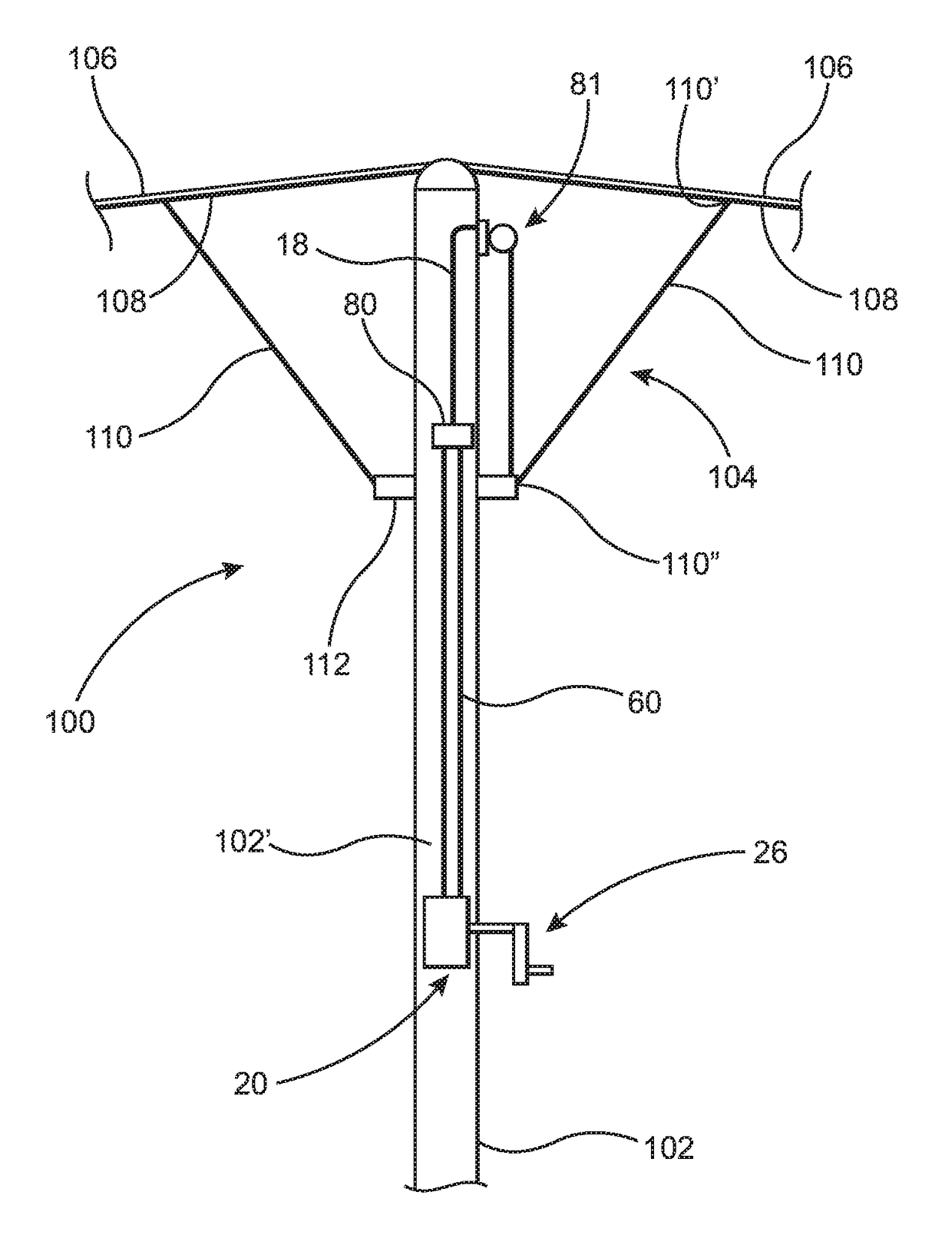
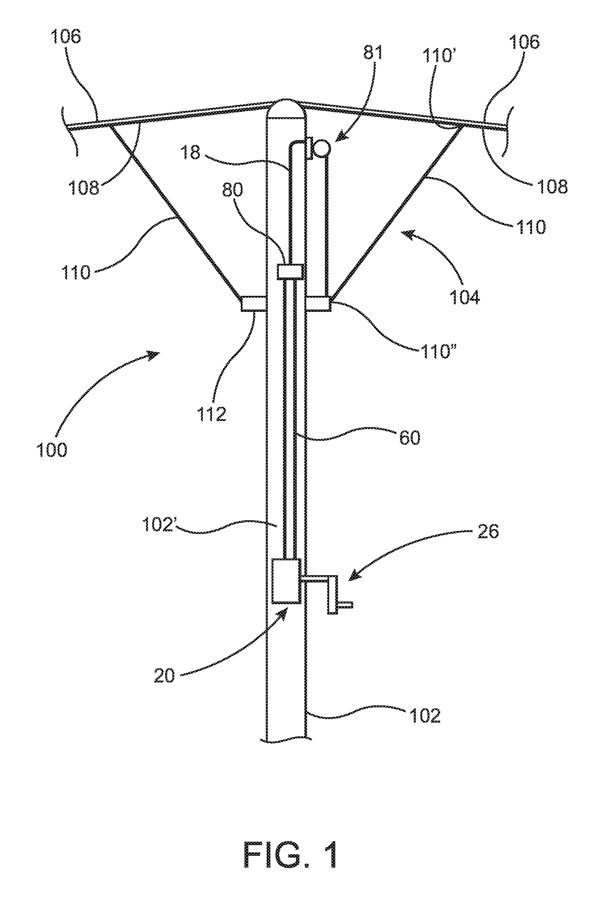
[0030]As represented in the accompanying Figures, the present invention is directed to a crank handle positioning assembly of the type to be used with an umbrella, such as but not limited to, a comparatively large outdoor umbrella. The versatility of the structural and operative features of the various preferred embodiments of the present invention facilitate its use with umbrellas of different structures, designs, dimensions and configurations.

[0031]However, and for purposes of illustration, the crank handle positioning assembly of the present invention will be described as being used in combination with an umbrella 100 of the type schematically represented in FIG. 1. As such, the umbrella 100 comprises a central mast, stanchion and / or center post 102, having an at least partially hollow interior 102′. The mast 102 is disposed in supporting relation to a canopy assembly generally represented as 104. Further, the canopy assembly 104 includes a flexible or foldable material canopy 10...


PUM


Abstract

A crank handle positioning assembly structured to selectively position a mast mounted canopy of an umbrella into and between open and closed orientations. A gear housing is disposed within the interior of the mast in at least partially enclosing relation to a gear assembly and in driving relation to at least one elongated drive gear. A crank handle is disposed on an exterior of the mast and extends there-through into rotationally driving relation to the gear assembly. A rider member is interconnected in driving relation to the canopy assembly and is reciprocally movable along the length of the drive gear upon rotational, driving engagement of the crank handle with the gear assembly. Concurrent, cooperative directions of linear movement of the rider member and a rotational movement of the crank handle is determinative of the positioning of the canopy assembly in either the open or closed orientations.

Description

CLAIM OF PRIORITY[0001]The present application is based on and a claim of priority is made under 35 U.S.C. Section 119(e) to a provisional patent application that is in the U.S. Patent and Trademark Office, namely, that having Ser. No. 61 / 992,557 and a filing date of May 13, 2014, and which is incorporated herein by reference.BACKGROUND OF THE INVENTION[0002]Field of the Invention[0003]This invention is directed to a crank handle positioning assembly for disposing a canopy assembly of an umbrella between open and closed orientations. A gear housing disposed within the interior of a mast of the umbrella encloses a gear assembly also within the interior of the umbrella mast, thereby eliminating any bulky housing or casing being disposed on the exterior of the mast.[0004]Description of the Related Art[0005]Comparatively large outdoor umbrellas are employed to shield people from the sun, wind, rain and other elements of nature. As such, they are intentionally designed and structured to ...

Claims


Application Information

Patent Timeline
IPC IPC(8): A45B25/14F16H25/20F16H57/038F16H57/021
CPCA45B25/14F16H57/021F16H57/038F16H25/20A45B2025/146F16H2025/2093
Inventor CLARKE, DOUGAN H.
Owner CLARKE DOUGAN H
Why Eureka
Try Eureka