Microfluidic grid-based design for high throughput assays

a microfluidic grid and high throughput technology, applied in the field of microfluidic grid-based design for high throughput assays, can solve the problems of long delay in the response time of integrated valves, interference with controlled comparisons between chambers, and significant flow non-uniformity in the original design, so as to improve the operation and reliability of the technology.

Inactive Publication Date: 2017-05-23
PALIWAL SAURABH +1
View PDF9 Cites 0 Cited by
  • Summary
  • Abstract
  • Description
  • Claims
  • Application Information

AI Technical Summary

Benefits of technology

[0014]Finally, we demonstrated that the 96-chamber ArrayChip device could be used in cell-based assays. We determined a full protocol to introduce cells, drug solutions, and visualization reagents into the device. Then, we ran a pilot experiment in which we exposed ACHN cells to various doses of an agonist and used immunofluorescence (with signaling-specific antibodies) to readout the response. This experiment was performed using typical equipment available to drug screening researchers, such as automated imaging platforms. We also identified potential improvements (e.g. increasing cell chamber height) that could further improve the operation and reliability of the technology.

Problems solved by technology

Through such experiments, we discovered significant flow non-uniformity in the originally proposed design.
This flaw caused flow rates to be different through different cell chambers, which would interfere with controlled comparisons between the chambers.
Another problem we encountered was long delays in the response time of integrated valves, which we eliminated by decreasing the length of the microchannels that control the valves.

Method used


Image

  • Microfluidic grid-based design for high throughput assays
  • Microfluidic grid-based design for high throughput assays
  • Microfluidic grid-based design for high throughput assays

Examples


Embodiment Construction

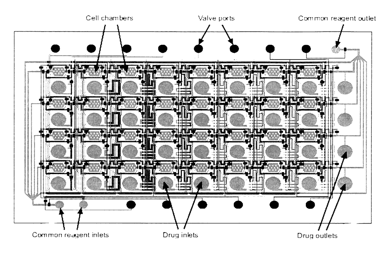
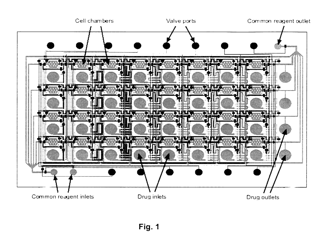
[0051]The result of this invention is a range of microfluidic chip design that would be appropriate for use in high-throughput drug screening applications, by designing it to be compatible with existing robotic liquid handlers and imaging equipment. To achieve this goal, we designed a microfluidic chip design in which the top-loading drug inlets and cell chambers are arranged in a grid spacing according to the ANSI / SBS standards for the locations of microtiter wells. In such a design, drugs can be transferred into the chip using standard fluid dispensers, and cell responses can be imaged with standard robotic microscopes. We performed three tasks to demonstrate the functionality of the design:[0052]Section A: Scale up the device design to accommodate 96- and 384-drugs in parallel[0053]Section B: Determine operating conditions and procedures that support cell experimentation[0054]Section C: Perform a pilot experiment to screen drugs on cells in the device

[0055]In the remainder of thi...


PUM

PropertyMeasurementUnit
sizeaaaaaaaaaa
sizeaaaaaaaaaa
heightaaaaaaaaaa

Abstract

Microfluidic devices have been developed to perform a range of high-throughput biochemical and cell-based assays over recent years. A design for a microfluidic device has been developed that resembles a microtiter plate, by placing the test chambers (each test chamber contains cells) and top-loading drug inlets (at least one per test chamber) in a grid according to the ANSI / SBS standards, yet offers the miniaturization and fluid handling advantages of microfluidics. This ensures that the device design is compatible with fluid handling and imaging equipment already in use for drug screening. A range of topologies have been determined that allow placement of various elements of this microfluidic network within the grid alignment constraints. A resistance equalization methodology has also been developed to reduce variability across assays run in different chambers of the microfluidic device. Additionally, it offers orders of magnitude miniaturization over multiwell plates, and potentially more reliable fluid handling.

Description

STATEMENT REGARDING FEDERALLY SPONSORED RESEARCH OR DEVELOPMENT[0001]This research was funded in part by a Small Business Innovation Research (SBIR) grant I P—1142913 from the National Science Foundation (NSF)CROSS-REFERENCE TO RELATED APPLICATIONS[0002]This application claims the benefit of U.S. Provisional Application No. 61 / 833,459 filed Jun. 11, 2013. The entire contents of the aforementioned application are hereby incorporated herein by reference.THE NAMES OF THE PARTIES TO A JOINT RESEARCH AGREEMENT[0003]Not ApplicableINCORPORATION-BY-REFERENCE OF MATERIAL SUBMITTED ON A COMPACT DISC OR AS A TEXT FILE VIA THE OFFICE ELECTRONIC HUNG SYSTEM (EFS-WEB)[0004]Not ApplicableSTATEMENT REGARDING PRIOR DISCLOSURES BY THE INVENTOR OR A JOINT INVENTOR[0005]Not ApplicableBACKGROUND OF THE INVENTION[0006]1) Field of the Invention[0007]The present invention relates to the general fields of microfluidics, cell based assays, and / or high-throughput assays.[0008]2) Description of Related Art Inc...

Claims


Application Information

Patent Timeline
Patent Type & Authority Patents(United States)
IPC IPC(8): B01L3/00C12N5/00
CPCB01L3/502761B01L3/502738C12N5/0018B01L2300/0829B01L2300/0864B01L2300/0874B01L2300/0883B01L2400/0487B01L2400/0655
Inventor PALIWAL, SAURABHYIN, ZHIZHONGCHEONG, RAYMOND
Owner PALIWAL SAURABH
Why Eureka
Try Eureka