Cam machine with adjustment mechanism

Pending Publication Date: 2022-06-02
BAHNEV BOYAN K
View PDF0 Cites 0 Cited by
  • Summary
  • Abstract
  • Description
  • Claims
  • Application Information

AI Technical Summary

Benefits of technology

This invention improves the operation and reliability of cam machines by creating new mechanisms for adjusting their kinematics and facilitating access to the control mechanism. The invention includes a functional insert in each plunger that can be adjusted using a monolithic or composed of several elements. The thickness of the functional insert is measured using a test insert with deformable elements, which is squeezed under the influence of the cam machine. The cam groove is designed to minimize the displacement of the additional bearing rollers along the main bearing rollers' axes, which reduces wear and tear and increases the length of service life of the cam machine. The integrated control mechanisms simplify the process of adjusting the cam machine.

Problems solved by technology

The cam mechanisms have limited applicability, mainly due to their mechanical wear.
It is caused due to friction between the followers and the cam and due to periodic interruptions of the contact between the followers and the cam profile and subsequent shock restoration of the contact.
However, significant problems appear in the described construction of the cam mechanism in D2.
One of the adjusting mechanism main problems in this case is the difficult access to the two position nuts, as the position nuts are located in the cylindrical cavities of the main bearing journals and the main bearing journals in turn are inside the compound cam.
However, it turns out that this connection is sufficient to be one-way, because the movement of the plunger is limited in the direction of the cam profile by the cam profile itself.
The two-way connection requires the use of more elements than necessary to build the mechanism for regulating the cam machine, which increases the weight of the followers and causes the appearance of greater inertial forces during operation of the cam machine.

Method used


Image

  • Cam machine with adjustment mechanism
  • Cam machine with adjustment mechanism
  • Cam machine with adjustment mechanism

Examples


Embodiment Construction

OF THE INVENTION

[0047]According to the invention, various double- or single-piston cam machines can be implemented, which perform different operating cycles depending on the user's need, and which cam machines can be compressors, pumps, internal combustion engines or combinations of the above.

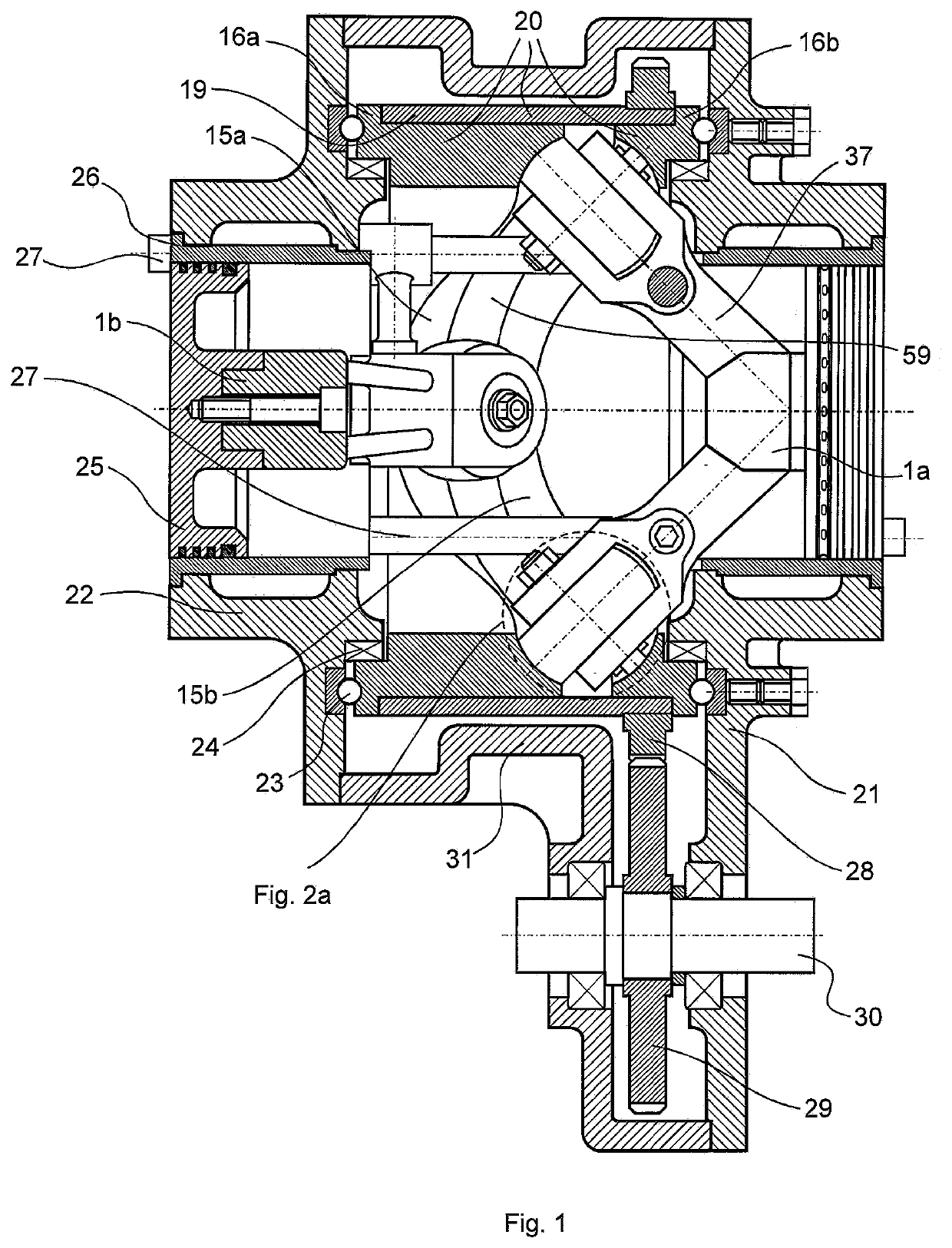
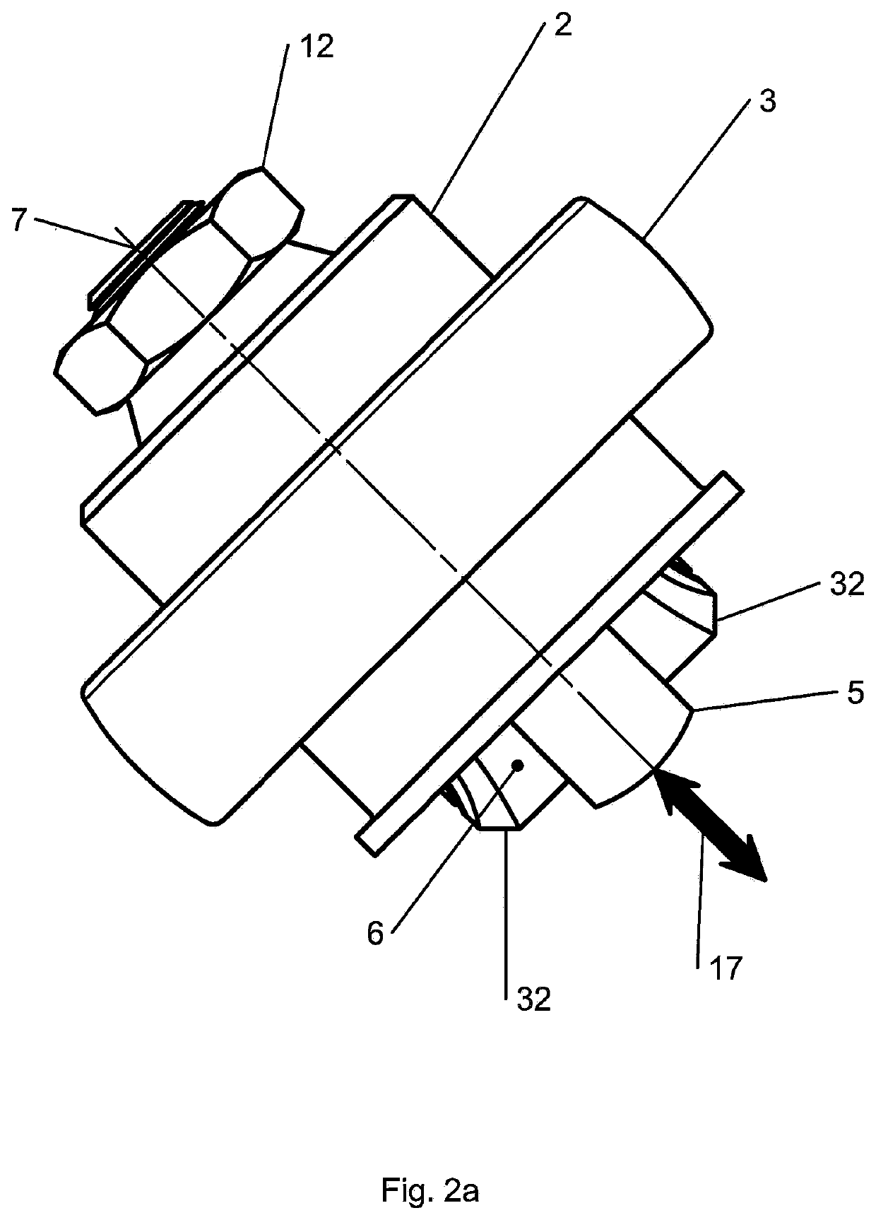
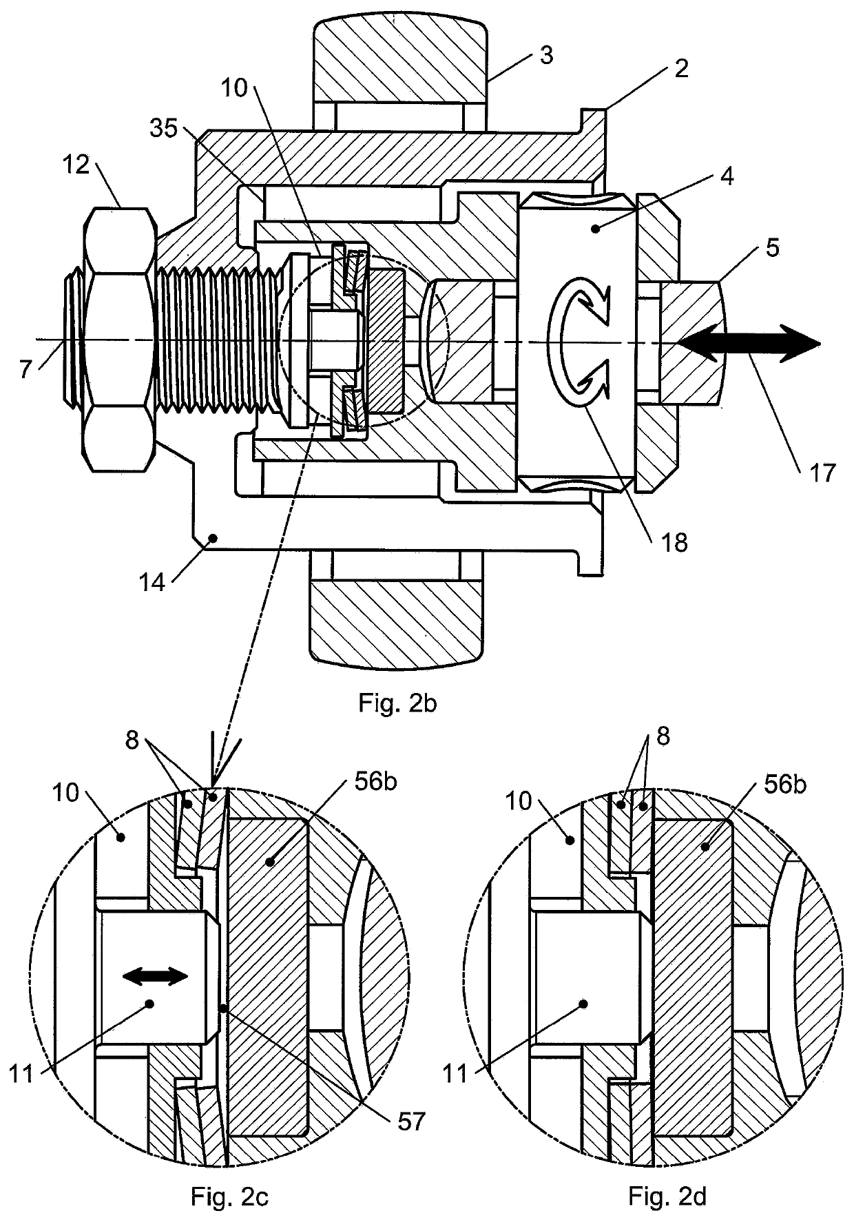
[0048]The created cam machine with adjusting mechanism shown in FIG. 1 includes a tubular 3D composite cam 20 which comprises cam bushings 16a and 16b and a tubular element 19 which orients the cam bushings 16a and 16b in such a way that their cam profiles 15a, 15b and the bottom 59, which is part of the tubular element 19, form a cam channel along the inner cylindrical surface of the 3D composite cam 20. The cam machine also comprises two identical followers 1a and 1b, each of which has two arms 37. Towards the free ends on the arms 37 main bearing journals 2 and main bearing rollers 3 are mounted. The main bearing journals 2 have a tubular geometry and in their cylindrical cavities additional...


PUM


Abstract

The invention relates to a cam machine with a control mechanism which will find application in various fields of mechanical engineering, such as compressor machines, hydraulic pumps, internal combustion engines and other types of engines in various land, sea and air vehicles, or in stationary units.The created cam machine improves the contact between the cam profiles (15a, 15b) of the cam bushings (16a, 16b) and the followers (1a, 1b). The main improvement of the machine is in the design of the regulating mechanism, which increases the reliability and the service life of the cam machine. In addition, simple and reliable control mechanisms are integrated in the machine, which at the same time simplifies the process of adjusting the cam machines.

Description

FIELD OF THE INVENTION[0001]The invention relates to a cam machine with an adjusting mechanism, which will find application in various fields of mechanical engineering, such as compressor machines, internal combustion engines and other types of engines used in various land, sea and air vehicles or in stationary units.BACKGROUND OF THE INVENTION[0002]The cam mechanisms area means of transforming movements with high precision and simplicity. The cam mechanisms have limited applicability, mainly due to their mechanical wear. It is caused due to friction between the followers and the cam and due to periodic interruptions of the contact between the followers and the cam profile and subsequent shock restoration of the contact.[0003]Cam mechanisms and machines are known in which the causes of the intensive wear of the cam mechanisms, which are disclosed in international applications PCT / BG2006 / 000017 (D1) and PCT / BG2012 / 000018 (D2), are partially eliminated. These cam mechanisms consist of...

Claims


Application Information

Patent Timeline
IPC IPC(8): F01B3/04F01B3/00F01B9/06F02B75/28
CPCF01B3/04F02B75/28F01B9/06F01B3/0002
Inventor BAHNEV, BOYAN KIRILOV
Owner BAHNEV BOYAN K
Why Eureka
Try Eureka