System for handling workpieces and method for operating such a system

a workpiece and workpiece technology, applied in the direction of non-positive displacement pumps, jet pumps, gripping heads, etc., can solve the problems of retrofitting of the system, and achieve the effects of rapid operation, increased productivity, and relatively slow change in vacuum level

Active Publication Date: 2017-05-23
J SCHMALZ GMBH
View PDF20 Cites 27 Cited by
  • Summary
  • Abstract
  • Description
  • Claims
  • Application Information

AI Technical Summary

Benefits of technology

[0012]The equipment in accordance with the claims makes it possible to arrange the vacuum generator or vacuum generators in the vicinity of the vacuum gripper. Therefore, the required paths for compressed air lines and vacuum lines are short. Therefore, for changes to the vacuum status in the vacuum grippers only short line sections have to be evacuated and / or loaded with pressure, which leads to distinctly shortened reaction times. In particular, the evacuation time for the vacuum gripper for gripping a workpiece can be distinctly shortened.
[0029]In particular, a storage device is provided in the evaluation unit, by means of which operating data of the vacuum generator and / or of the handling device is stored. In particular, recognition data (also viewed as operating data) is deposited in the storage device which identifies the handling device. In so far the evaluation unit can also act as a recognition unit for the handling device. Therefore, in an exchange of the handling device in the system the recognition data can be directly read out, which simplifies the configuration process.

Problems solved by technology

A retrofitting of the system is often associated with undesirably long standstill times.

Method used


Image

  • System for handling workpieces and method for operating such a system
  • System for handling workpieces and method for operating such a system
  • System for handling workpieces and method for operating such a system

Examples


Embodiment Construction

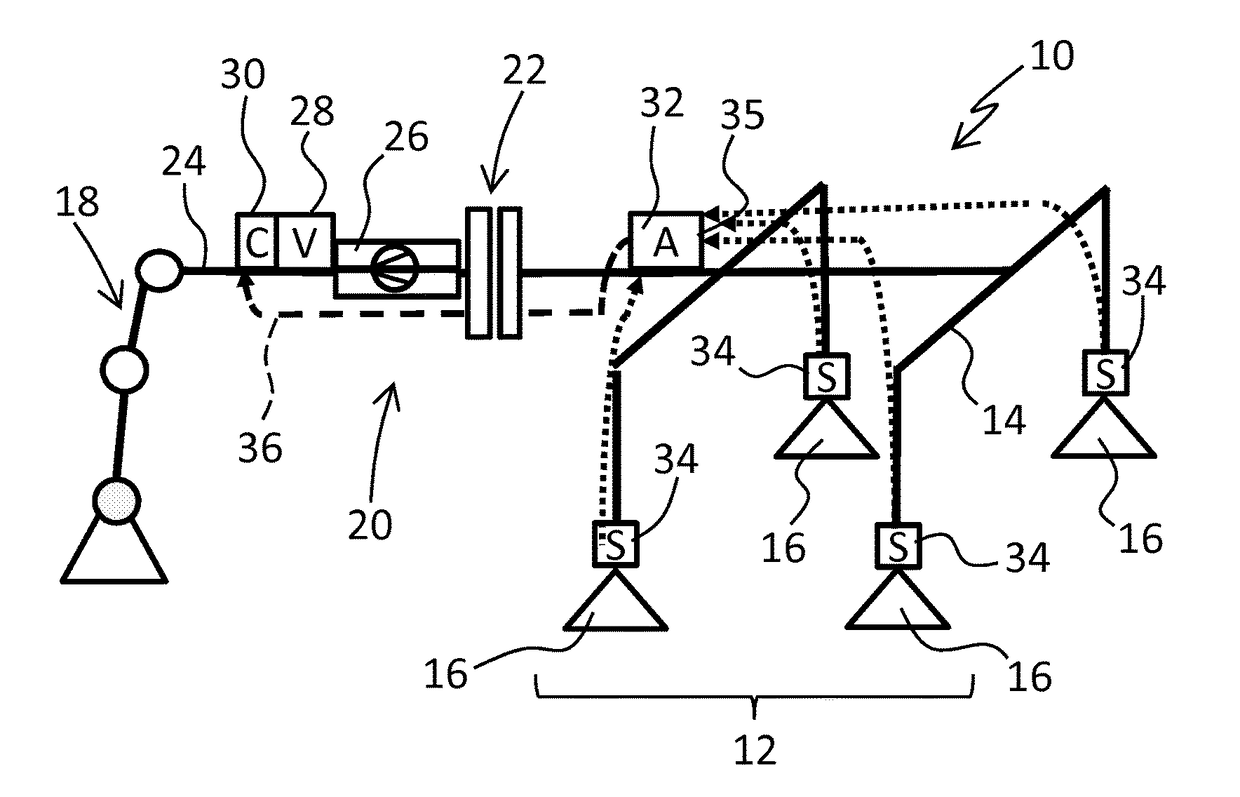
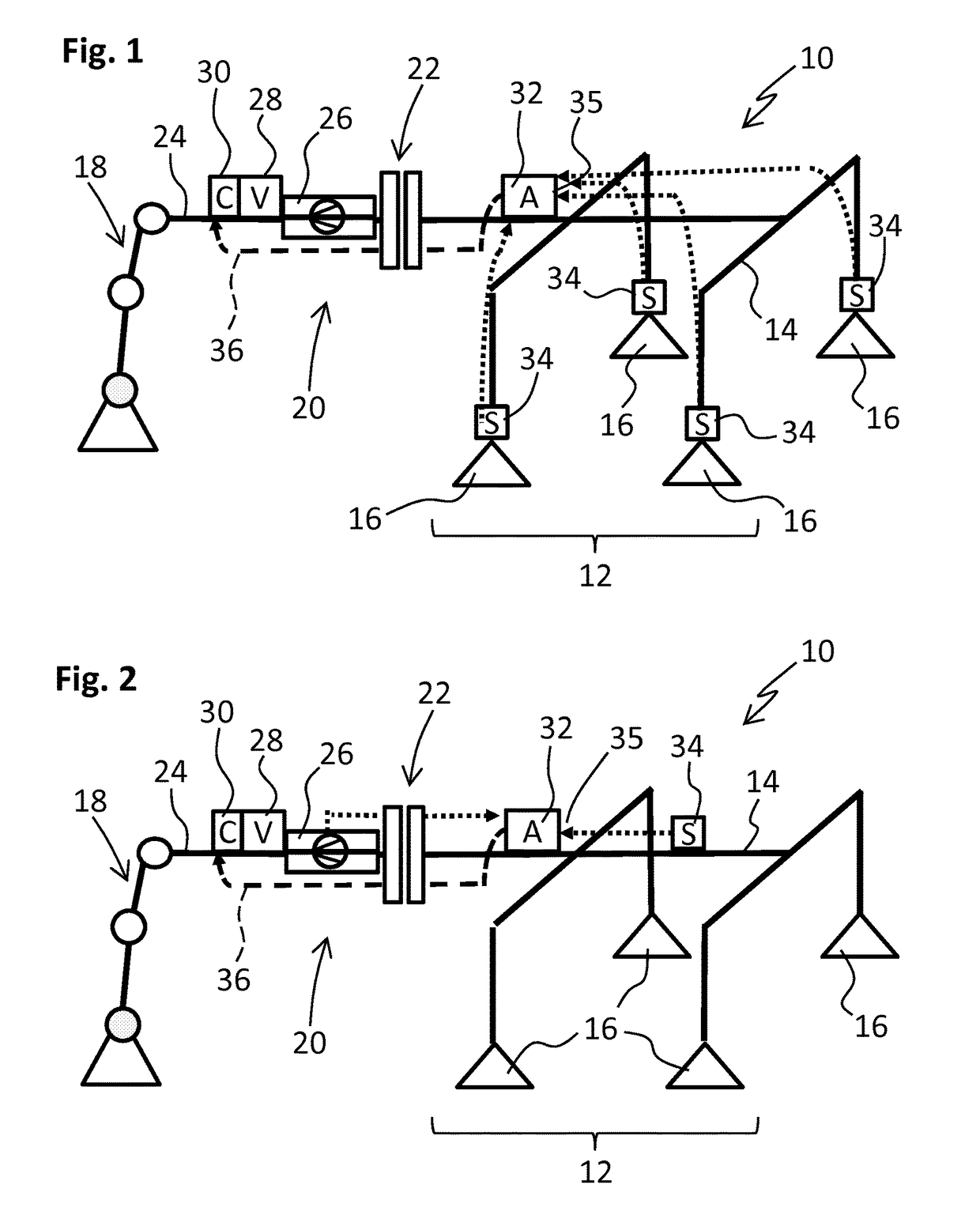
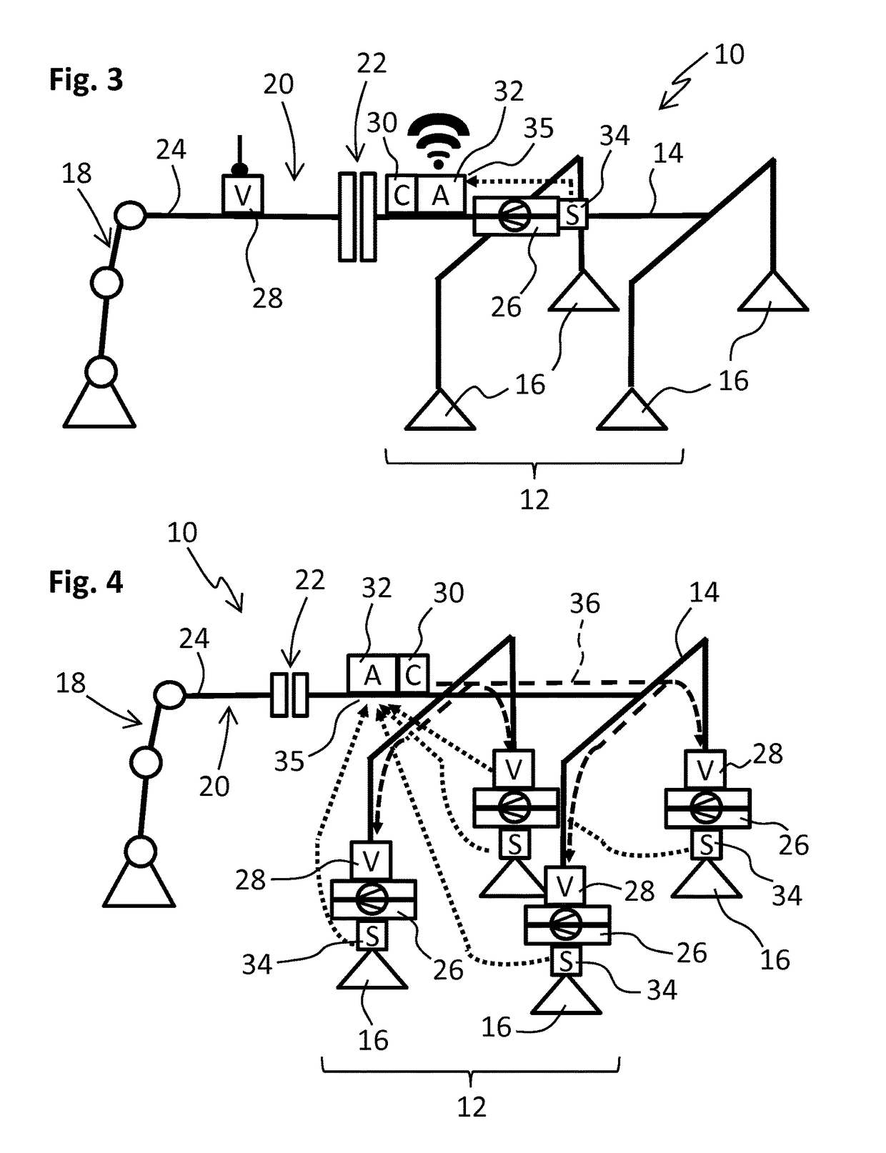
[0044]FIGS. 1 to 4 show a system 10 for handling a workpiece that is not shown in detail. The system 10 comprises a handling device 12 constructed in the example shown as a suction spider. The handling device 12 comprises a carrier 14 like a framework on which a plurality of vacuum grippers (here: suction grippers) 16 for fixing the workpiece are arranged.

[0045]The system 10 also comprises an actuator 18 which is shown like a sketched robotic arm. This arm serves to move the handling device 12. The handling device 12 is arranged on a holding section 20 of the actuator 18 in such a manner that that it can be fastened and detached by a rapid replacement coupling 22. To this end the rapid replacement coupling comprises a coupling section (shown in the figures by vertical beams) on the carrier 14 and one on the holding section 20.

[0046]The system 10 comprises a compressed air supply system 24 that is not shown in detail that is supplied from the actuator 18 in the examples shown. The va...


PUM


Abstract

The invention relates to a system (10) for handling workpieces, with a handling device (12) which comprises at least one vacuum gripper (16) for drawing a workpiece in by suction, with at least one vacuum generator (26) that can be operated by the supply of compressed air for supplying the vacuum gripper (16) with vacuum, with at least one controllable control valve (28) by which the supply of compressed air to the vacuum generator (26) can be controlled, wherein the control valve (28) is associated with a control device (30) for the proper control of the control valve (28 as required. The handling device comprises an evaluation unit (32) for evaluating operating data of the vacuum generator (26) and / or for evaluating operating data of the handling device (12) as well as for generating control signals as a function of the evaluated operating data, wherein the evaluation unit (32) is arranged on the handling device (12), and wherein the control device (30) controls the control valve (28) as a function of the control signals transmitted from the evaluation unit (32).

Description

BACKGROUND OF THE INVENTIONField of Invention[0001]The invention relates to a system for handling workpieces and to an operating method.[0002]Such systems can be used, e.g. in production assembly lines or processing assembly lines. The systems comprise in particular a handling device with which a workpiece can be fixed or grasped. The handling device itself can be complexly constructed, e.g. it can comprise a plurality of vacuum grippers. Furthermore, an actuator is often provided, e.g. a robotic arm that is coupled to the handling device in order to move it.SUMMARY OF THE INVENTION[0003]The present invention relates in particular to pneumatically operated systems that comprise at least one vacuum generator (e.g., driven by compressed air) which supplies the handling devices (e.g. vacuum grippers) with the required vacuum. During the operation of such systems the individual functional units must be coordinated with each other. In particular, the operating data of the handling device...

Claims


Application Information

Patent Timeline
Patent Type & Authority Patents(United States)
IPC IPC(8): B65G47/91B25J15/06B25J15/00F04F5/52
CPCB65G47/917B25J15/0061B25J15/0616B25J15/0625B25J15/0675B65G47/91F04F5/52B65G47/918
Inventor DUNKMANN, WALTERHOLECEK, THOMAS
Owner J SCHMALZ GMBH
Why Eureka
Try Eureka