
Method for operating a combined cycle power plant, and combined cycle power plant

a combined cycle and power plant technology, applied in the direction of electric generator control, greenhouse gas reduction, instruments, etc., can solve the problems of reducing the efficiency of the wind turbine on the whole, reducing the power taking a few hundred milliseconds, if not even seconds, so as to achieve the effect of increasing the power consumption of the power-to-gas unit, reducing the power consumption, and increasing the power consumption

Inactive Publication Date: 2015-04-16
WOBBEN PROPERTIES GMBH
View PDF3 Cites 25 Cited by
  • Summary
  • Abstract
  • Description
  • Claims
  • Application Information

AI Technical Summary

Benefits of technology

This patent aims to improve the previous support of the grid by reducing the reaction time when a predetermined grid frequency value is undershot or when a determined frequency drop gradient is exceeded. It also aims to provide electrical power increase for a longer period of time to better support the grid and contribute to frequency stability.

Problems solved by technology

If, however, the consumption exceeds the generation, that is to say if more electrical power is drawn from the grid than is fed into the electrical grid, the grid frequency thus decreases.
Wind turbines or also solar facilities, which generate electrical power, are indeed able to operate in a grid-supporting manner in a particular way in the event of underfrequency, however this is often insufficient.
It has already been proposed to operate wind turbines below their optimum, that is to say below their power curve, such that, in the case of an underfrequency, a power reserve can be connected, however such a solution is not very effective because it also means that, for the period of time in which the first predetermined grid frequency is not undershot, the energy or power yield of the wind turbine is only suboptimal and therefore a large amount of electrical power that could be supplied by wind energy is not even generated, which considerably reduces the efficiency of the wind turbine on the whole.
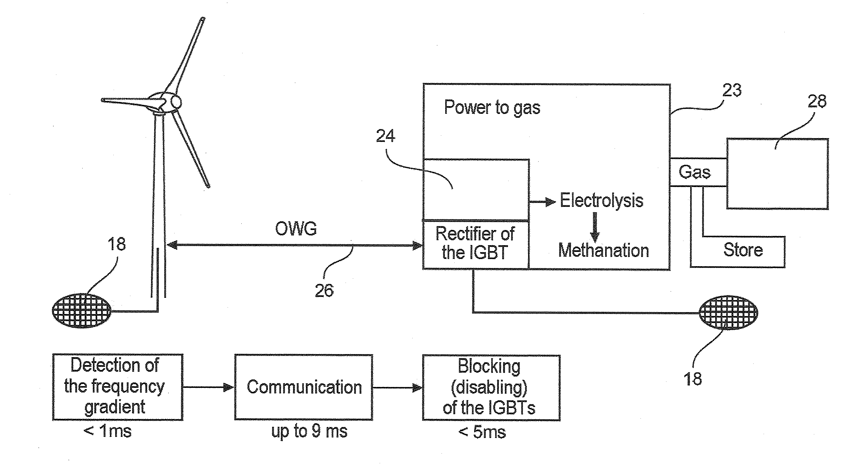
Here, it is also problematic that it takes a few hundred milliseconds, if not even seconds, until the increased power consumption can be provided following triggering of the switching event for example undershooting of the first predetermined grid frequency value, for example 49.7 Hz and / or exceeding a predetermined frequency gradient (ΔF / Δt).

Method used


Image

  • Method for operating a combined cycle power plant, and combined cycle power plant
  • Method for operating a combined cycle power plant, and combined cycle power plant
  • Method for operating a combined cycle power plant, and combined cycle power plant

Examples


Embodiment Construction

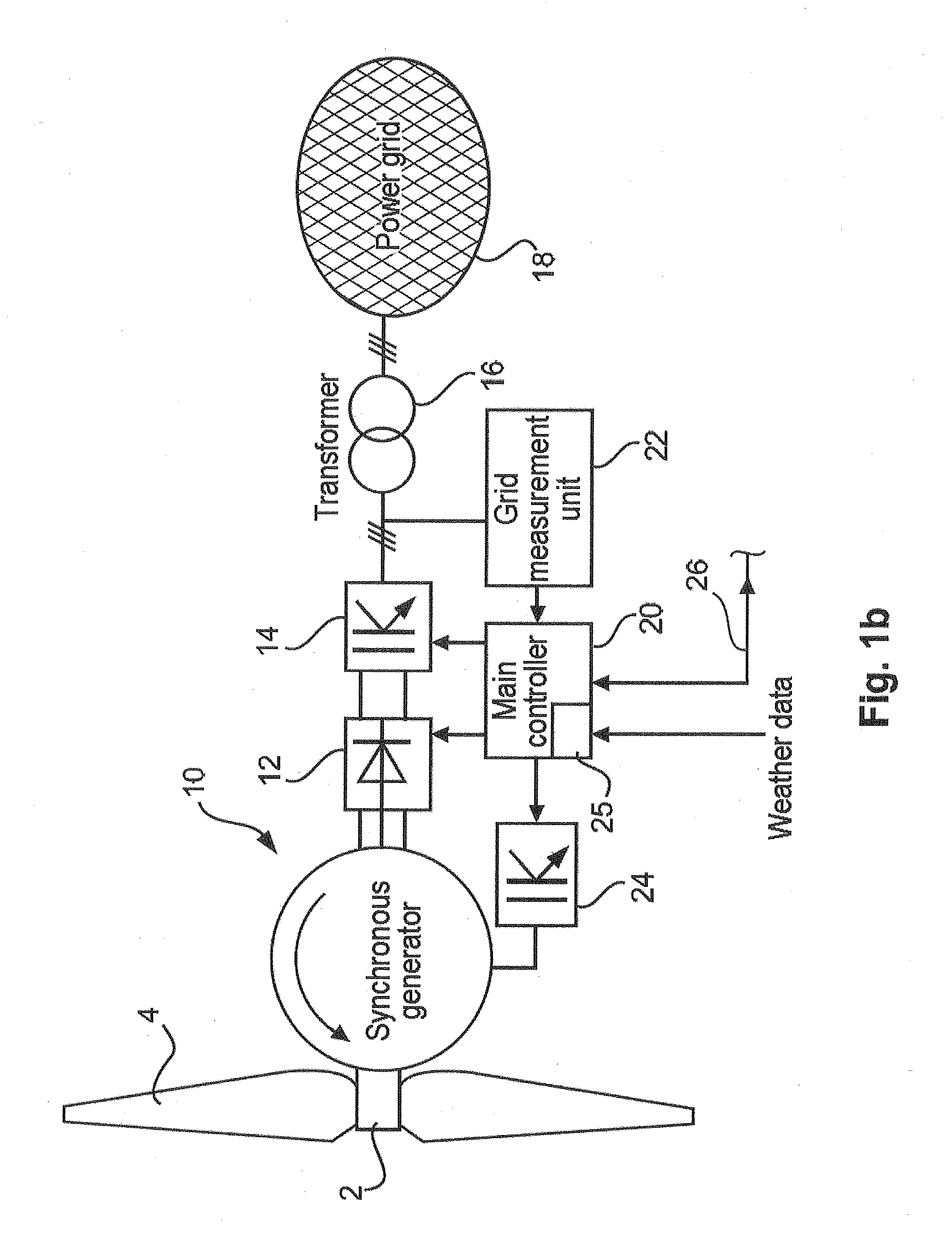
[0063]Like reference signs may denote like or also similar, non-identical elements hereinafter. Hereinafter, for the sake of completeness, a wind turbine with a synchronous generator and gearless concept with a full power convertor will be explained.

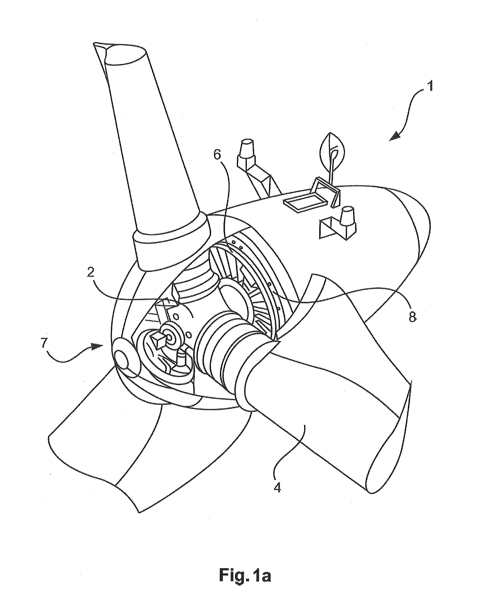
[0064]FIG. 1a schematically shows a nacelle 1 of a gearless wind turbine. The hub 2 can be seen due to the fact that the casing (spinner) is illustrated in a partly open manner. Three rotor blades 4 are fastened to the hub, wherein the rotor blades 4 are illustrated only in their region close to the hub. The hub 2 with the rotor blades 4 forms an aerodynamic rotor 7. The hub 2 is mechanically fixedly connected to the rotor 6 of the generator, which can also be referred to as an armature 6 and will be referred to hereinafter as the armature 6. The armature 6 is mounted rotatably with respect to the stator 8.

[0065]The armature 6 is energized during its rotation relative to the stator 8, usually with a direct current, in order to thus gener...


PUM


Abstract

The invention relates to a method for operating a power-to-gas arrangement that is to say an arrangement which generates a gas, for example hydrogen and / or methane and / or the like, from electrical energy, wherein the power-to-gas unit for generating the gas draws electrical energy from an electrical grid, to which the power-to-gas unit is connected, wherein the grid has a predetermined setpoint frequency or a setpoint frequency range, wherein the power-to-gas unit reduces the consumption of electrical power by a predetermined value or consumes no electrical power when the grid frequency of the electrical grid is below the desired setpoint frequency of the grid by a predetermined frequency value and / or when the grid frequency drops with a frequency gradient, specifically with a change over time (Δf / Δt), of which the magnitude exceeds a predetermined magnitude of change.

Description

BACKGROUNDDescription of the Related Art[0001]Wind turbines have long been known and used in a variety of ways.[0002]Wind turbines are present as standalone systems or as wind farms, comprising a plurality of individual wind turbines. It is increasingly required of such power generation facilities, such as wind turbines, but also solar plants and the like, that when the frequency of the electrical grid into which the wind turbine, the wind farm or the solar plant feeds its electrical power falls below a specific grid frequency value, which is below the setpoint value, to feed an increased power contribution into the grid in order to support the grid in this way.[0003]As is known, the setpoint frequency of an electrical grid in the German or European interconnected grid is 50 Hz, and in the USA is 60 Hz. Other countries have adopted corresponding regulations.[0004]This setpoint frequency can be achieved relatively well when the power drawn by the consumers connected to the grid is ap...

Claims


Application Information

Patent Timeline
Patent Type & Authority Applications(United States)
IPC IPC(8): G05F1/66F03D9/00
CPCG05F1/66F03D9/005Y02E70/30H02J3/28F03D9/10F03D9/257Y02P90/50H02J2300/40H02J2300/10H02J2300/28H02J2300/20H02J3/381Y02E10/50Y02E10/72Y02E10/76H02J3/241H02J15/008F03D9/11H02J3/30Y02T70/5236H02S10/12F03D9/007
Inventor BEEKMANN, ALFRED
Owner WOBBEN PROPERTIES GMBH
Learn More