Radio-controlled clock, receiver circuit and method for acquiring time information with economized receiver and microcontroller

a receiver circuit and time information technology, applied in the direction of electronic time-pieces, instruments, optics, etc., can solve the problems of large circuit size, large circuit technology, and large circuit and achieve the reduction of the chip surface area of the receiver circuit correspondingly, the effect of reducing the effort and expenditure of the receiver circui

Inactive Publication Date: 2005-08-04
ATMEL GERMANY
View PDF19 Cites 25 Cited by
  • Summary
  • Abstract
  • Description
  • Claims
  • Application Information

AI Technical Summary

Benefits of technology

[0037] Thus, a special advantage of the present invention is that the individual data bits acquired through the evaluation or decoding carried out in the receiver no longer need to be stored in a suitably provided memory in the receiver circuit. For this reason, the circuit effort and expenditure for the receiver circuit are significantly reduced. The chip surface area of the receiver circuit can be correspondingly reduced, whereby the receiver circuit and thus the entire radio-controlled clock including such a receiver circuit can be produced more economically. Thus, in competition among circuit components and finished products that have essentially the same functions, as is the case in the field of radio-controlled clocks, it is a great competitive advantage to produce the circuit components and the radio-controlled clocks with reduced effort and at lower cost.
[0038] A further advantage of the invention is that the number of the required external connection terminals or pins of the receiver can be reduced. Particularly, the receiver circuit according to the invention (in comparison to conventional receiver circuits) no longer needs a pin for receiving a request for data (i.e. a data request pin), as well as a pin for signaling that valid data are available in the memory (i.e. a data ready pin). Moreover, the system clocking signal or timing pulse signal of the microprocessor can simply be directly used as a read-out timing pulse for reading-out the acquired data bits.
[0039] It is further especially advantageous according to the invention, that the reaction time of the radio-controlled clock and especially the receiver thereof is significantly reduced, because the decoded data bits are continuously output in succession by the receiver circuit during, or at the end of, or immediately following the end of each time frame, rather than waiting until all of the data bits of a respective complete minute telegram of the received time signal have been decoded and are available in an intermediate memory.
[0040] In a first alternative embodiment of the inventive method, the determination and outputting or transmission of a respective individual data bit is carried out still within or during the receiving of the time frame to which this respective data bit is allocated. This is possible because the pertinent time information is typically contained at the beginning of a time frame and does not take up the entire duration of that time frame. Namely, the corresponding second pulse representing the time information is typically given by a temporary variation of the amplitude of the time signal at the beginning of the respective associated time frame of the time signal. Typically, but not absolutely necessarily, no time information is present at the very end of a given time frame of the time signal.
[0041] For example, the German time signal transmitted by the German transmitter DCF-77 contains respective temporary dips or reductions of the amplitude, i.e. second pulses, having a duration of 100 msec or 200 msec directly at the beginning of a respective time frame that has a 1000 msec duration. Thus, depending on the duration of a given second pulse, the evaluating arrangement or decoder of the receiver has either 900 msec or 800 msec of time available during the time frame in order to evaluate or decode the amplitude modulated time information contained in the second pulse at the beginning of this time frame, and to still output the corresponding determined data bit during this time frame. In other words, once the second pulse has been detected and recognized as completed within the first 100 or 200 msec of the time frame, the remaining duration of the time frame is available for the receiver to carry out the evaluation and then the outputting of the corresponding data bit still during the current time frame.
[0042] According to a second alternative embodiment of the inventive method, the transmission of a respective data bit allocated to a particular time frame is transmitted or output by the receiver during a further time frame following the particular time frame to which the data bit is allocated. In this regard it is especially advantageous if the respective data bit is transmitted or output during the immediately next time frame, and especially at the beginning of the immediately next time frame that directly follows the particular time frame to which the data bit is allocated. Thus, the description that a data bit is outputted “directly after” an end of a time frame encompasses outputting that data bit at any time during the next successive time frame.

Problems solved by technology

Thus, the computational resources of the microcontroller, which are quite limited already from the beginning, are generally not available or only available in a very limited degree for other tasks.
As a result, the time signal receiver, which is embodied as an integrated circuit, becomes relatively complicated and costly in terms of the circuit technology, circuit size, etc.
Furthermore, it is problematic that there is a relatively long reaction time between switching-on the radio-controlled clock and the first reaction of the time signal receiver to the time information received in the time signal.

Method used


Image

  • Radio-controlled clock, receiver circuit and method for acquiring time information with economized receiver and microcontroller
  • Radio-controlled clock, receiver circuit and method for acquiring time information with economized receiver and microcontroller
  • Radio-controlled clock, receiver circuit and method for acquiring time information with economized receiver and microcontroller

Examples


Embodiment Construction

[0064] In all of the drawing figures, the same elements and signals, as well as the elements and signals respectively having the same functions, are identified by the same reference numbers, unless the contrary is indicated.

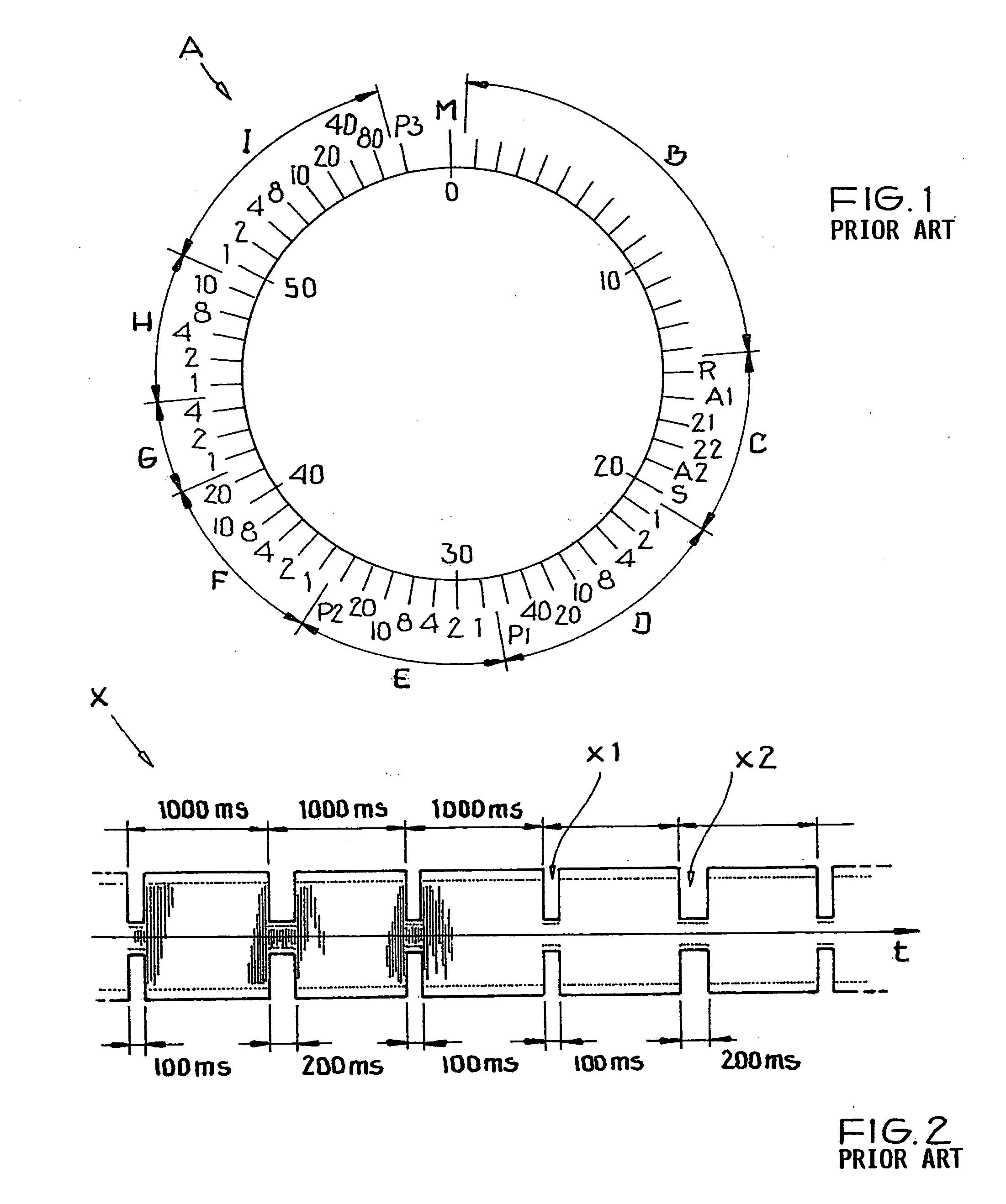
[0065] The general format of an encoding scheme or time code telegram A as conventionally known in the time signal transmitted by the German time signal transmitter DCF-77 has been explained above in connection with FIG. 1 in the Background Information section of this specification. Also, the time-variation of the amplitude-modulated time signal is schematically shown in the time diagram of FIG. 2 as discussed above.

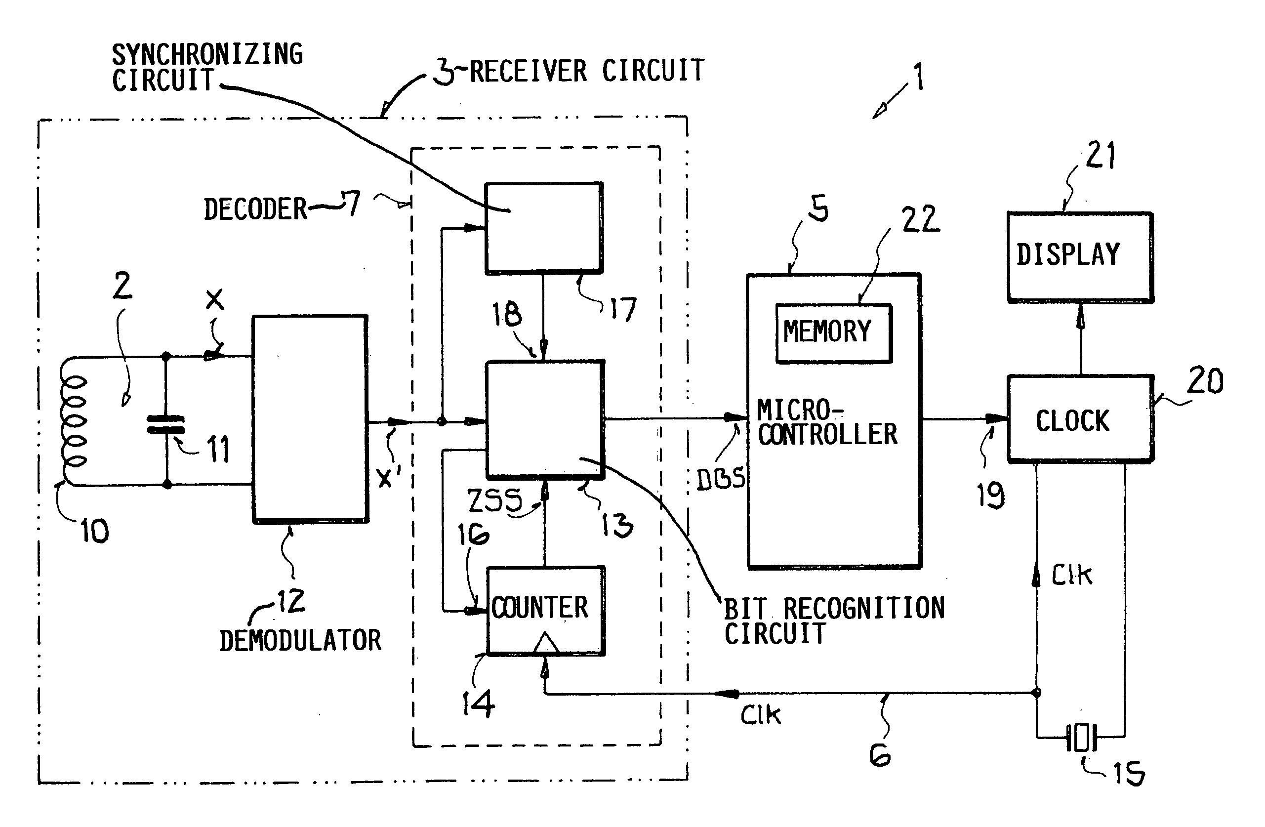
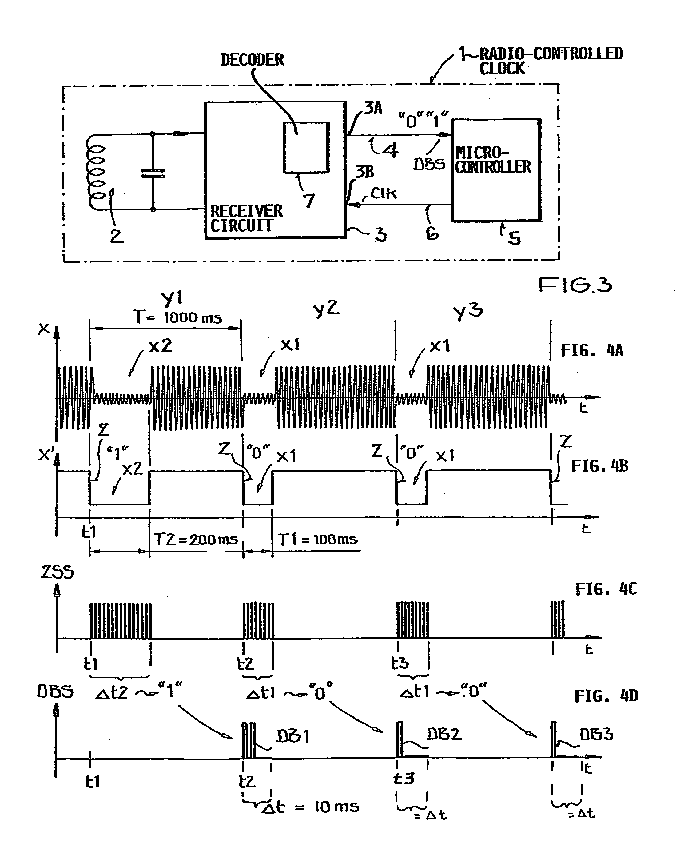
[0066]FIG. 3 is a significantly simplified schematic block circuit diagram of a portion of a radio-controlled clock 1 for carrying out the method according to the invention. The radio-controlled clock 1 comprises a receiving antenna 2 for receiving the time signal X transmitted from a time signal transmitter which is not shown. A receiver circuit 3 ...


PUM


Abstract

A transmitted time signal carries time information encoded bit-wise by signal amplitude variations in a succession of time frames. A method involves receiving and evaluating the time signal in a receiver to acquire the time information, and then outputting from the receiver an individual data bit respectively allocated to a respective time frame during or at the end of or immediately after the respective time frame. It is not necessary to store all the data bits of a complete minute telegram in the receiver before the evaluation. The successive data bits are used by a microprocessor downstream from the receiver to produce a time signal. A circuit arrangement for a radio-controlled clock includes a receiving antenna connected to a receiver circuit that incorporates a time information decoder for decoding the time information contained in the time signal. The decoder provides, at an output of the receiver circuit, the decoded data bit allocated to a time frame, already during, at the end of, or immediately after the end of that time frame.

Description

CROSS-REFERENCE TO RELATED APPLICATION [0001] This application is related to U.S. application Ser. No. 10 / 910,261, filed on Aug. 2, 2004, the entire disclosure of which is incorporated herein by reference.PRIORITY CLAIM [0002] This application is based on and claims the priority under 35 U.S.C. §119 of German Patent Application 10 2004 005 340.5, filed on Feb. 4, 2004, the entire disclosure of which is incorporated herein by reference. FIELD OF THE INVENTION [0003] The invention relates to a method for acquiring time information from a received amplitude-modulated time signal. The invention further relates to a radio-controlled clock and a receiver circuit for a radio-controlled clock, especially for carrying out such a method. BACKGROUND INFORMATION [0004] It is conventionally known to provide time reference information in time signals that are transmitted by radio transmission from a time signal transmitter. Such a signal may also be called a time marker signal, a time data signal...

Claims


Application Information

Patent Timeline
Patent Type & Authority Applications(United States)
IPC IPC(8): G02C11/02G04G5/00G04R20/10G04R20/12H04J3/00
CPCG04G5/002G04R20/12G04R20/10
Inventor HAEFNER, HORST
Owner ATMEL GERMANY
Why Eureka
Try Eureka