
Method of producing vapor-grown carbon fibers

a technology of carbon fiber and vapor growth, which is applied in the direction of carbonsing rags, material nanotechnology, textiles and papermaking, etc., can solve the problems of inability to obtain significant yield of carbon fiber and inability to produce good efficiency of carbon fiber, and achieves short reaction time, high yield, and high efficiency in effective use of catalyst or catalyst precursor

Inactive Publication Date: 2010-04-27
RESONAC HOLDINGS CORPORATION
View PDF7 Cites 25 Cited by
  • Summary
  • Abstract
  • Description
  • Claims
  • Application Information

AI Technical Summary

Benefits of technology

The present invention relates to a method for producing vapor-grown carbon fibers using a combination of two types of compounds, namely, a carbon compound and an aromatic compound. By using this combination, the reaction time is shortened and the efficiency of the catalyst is improved, resulting in a higher yield of carbon fibers. The ratio of the number of atoms of the element of catalyst to the number of carbon atoms is important and can affect the efficiency of the catalyst. The method is efficient and effective in producing carbon fibers with good efficiency.

Problems solved by technology

In the case where only the compound of Group (a) is used, a fiber is produced but it grows slowly in the diameter direction and, as a result, the carbon fibers cannot be produced with good efficiency.
On the other hand, when the compound of Group (b) is used alone, fibers are not satisfactorily produced in the low-temperature region and the catalyst is mostly aggregated and loses the catalytic ability and, as a result, carbon fibers cannot be obtained in a significant yield unless a large excess of a catalyst or catalyst precursor is fed.

Method used


Image

  • Method of producing vapor-grown carbon fibers
  • Method of producing vapor-grown carbon fibers
  • Method of producing vapor-grown carbon fibers

Examples


example 1

a: Ethylene, b: Benzene

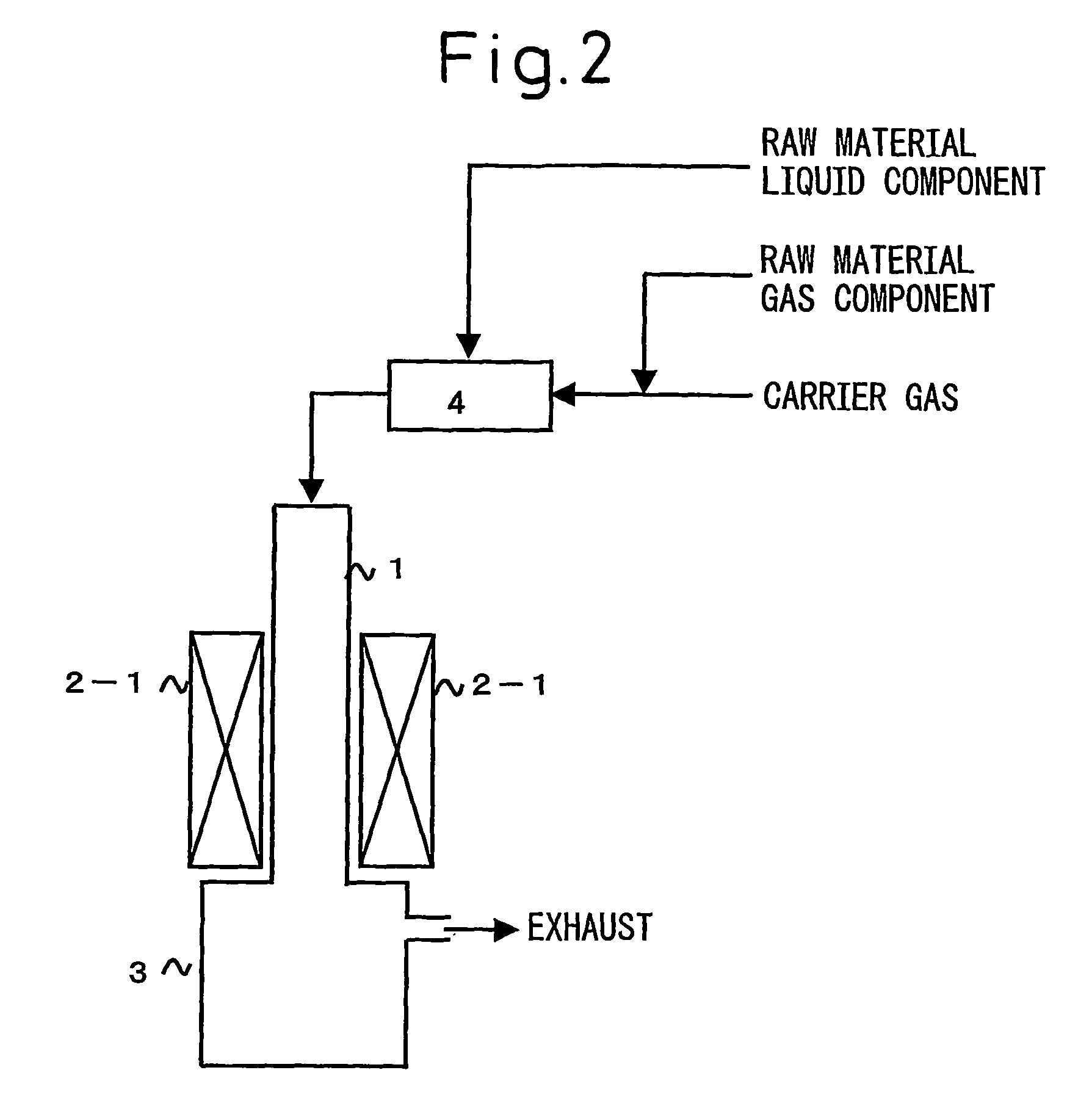
[0118]In a vertical furnace equipped with a quartz reaction tube 1 (inside diameter: 31 mm, outside diameter: 36 mm, length of heating zone: about 400 mm) shown in FIG. 2, the temperature in the heating zone was elevated to 1,250° C. in an N2 gas stream and then, after stopping the feeding of N2, H2 as a carrier gas was instead passed at 1 NL / min into the reaction tube. When the temperature was stabilized, ethylene (a compound of Group (a)) was mixed in the gas state with H2. A solution obtained by dissolving and mixing benzene (a compound of Group (b)), ferrocene and thiophene was introduced by using a small pump into a vaporizer 4 heated to 200° C. for 10 minutes, to vaporize in an amount, of each component shown in Table 1, and the resulting gas was caused to accompany the mixed gas of H2 and ethylene. In this way, all compounds were fed in the gas state into the reaction tube.

[0119]As a result of the reaction, a gray-tinged cobweb-like deposit was produced...

example 2

a: Methane, b: Benzene

[0120]The reaction was performed according to the method of Example 1 except for using methane in place of ethylene. The results are shown in Table 1. The product was a fibrous material having an average outside diameter of 150 nm and the carbon recovery was 35%.

example 3

a: Carbon Monoxide, b: Benzene

[0121]The reaction was performed according to the method of Example 1 except for using carbon monoxide in place of ethylene. The results are shown in Table 1. The product was a fibrous material having an average outside diameter of 150 nm and the carbon recovery was 34%.


PUM

PropertyMeasurementUnit
diameteraaaaaaaaaa
temperatureaaaaaaaaaa
boiling pointaaaaaaaaaa

Abstract

A method for producing vapor-grown carbon fibers, comprising contacting a carbon compound with a catalyst and / or a catalyst precursor compound in a heating zone, wherein the carbon compound is a combination of compounds respectively selected from carbon compounds having no benzene ring structure within molecule [Group (a)] and from aromatic compounds [Group (b)], these compounds satisfy the conditions that, in the raw materials, (number of atoms of element as catalyst) / (number of all carbon atoms) & equals; 0.000005 to 0.0015 and [number of carbon atoms contained in compound of Group (a)] / [number of carbon atoms contained in compound of Group (a)+number of carbon atoms contained in compound of Group (b)]& equals; 0.001 to 0.9, and the residence time in the temperature region of 600° C. or more is 30 seconds or less.

Description

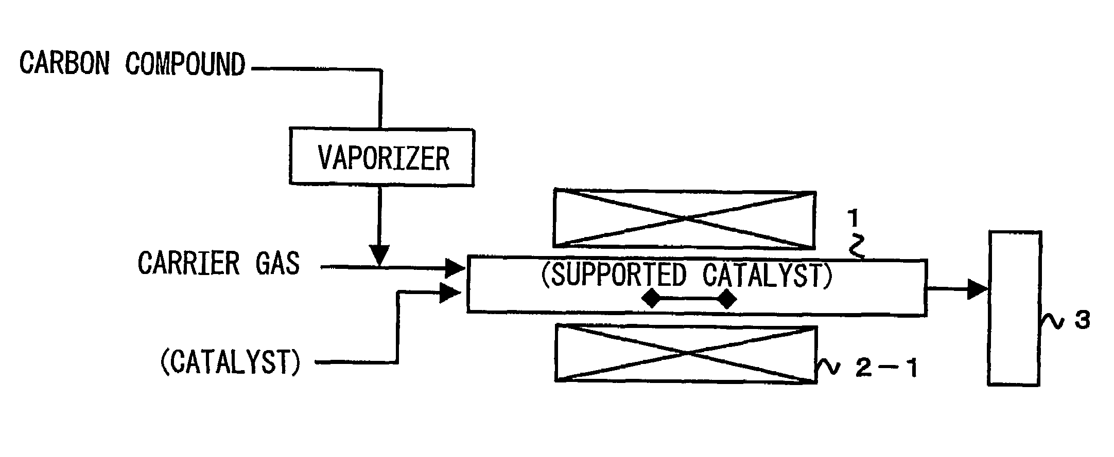
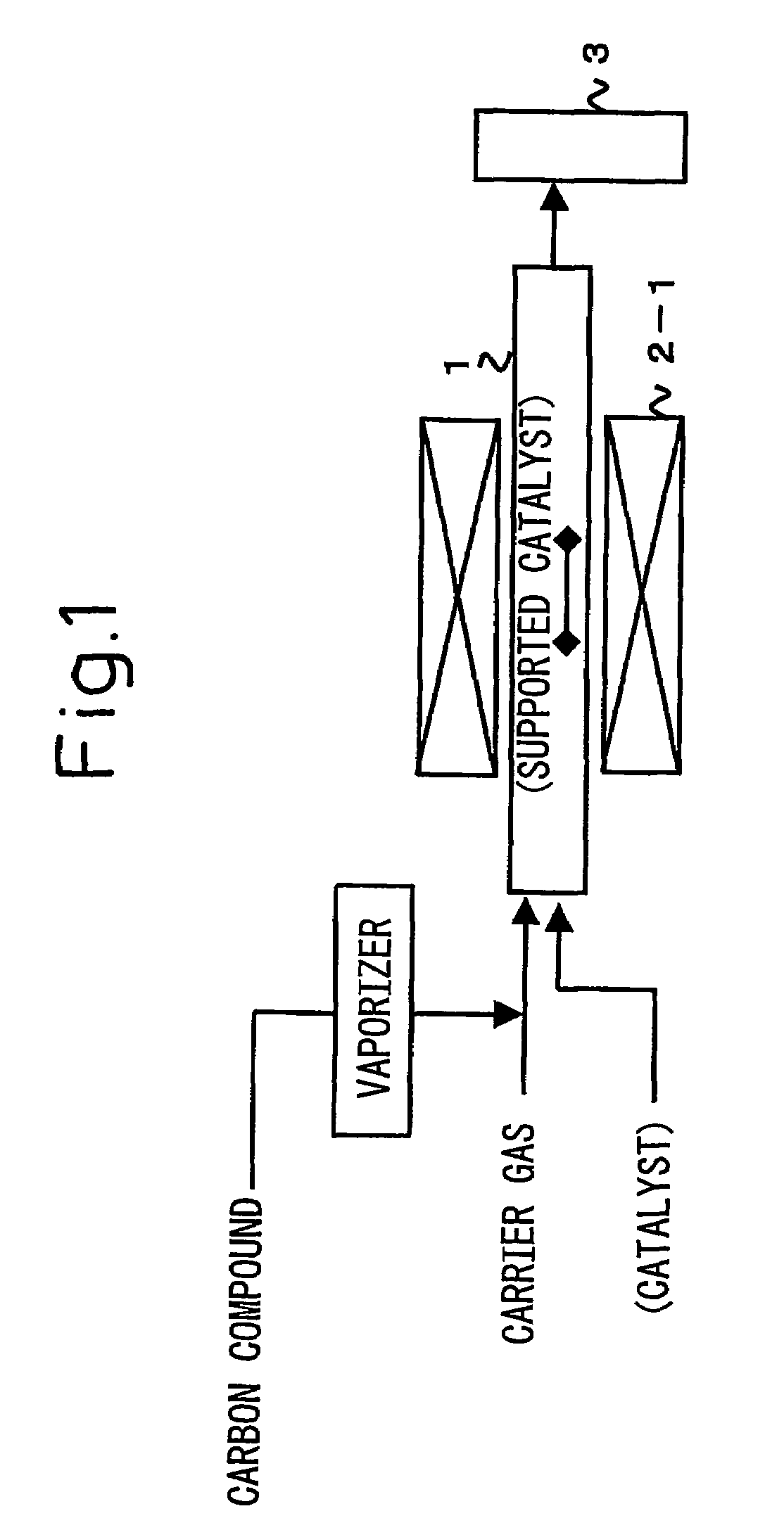
TECHNICAL FIELD[0001]The present invention relates to a method for efficiently producing vapor-grown carbon fibers such as carbon nanotubes.BACKGROUND ART[0002]Heretofore, studies have been aggressively made on the carbon fibers obtained by the vapor-growth process (vapor-grown carbon fibers) because carbon fibers having a high aspect ratio can be relatively easily obtained, and many proposals have been reported also on the production method therefor. The carbon nanotubes (that is, carbon fibers having a fiber diameter on the nanometer order) which are, in particular, recently attracting attention can also be synthesized by applying this vapor-growth process.[0003]FIG. 1 is a schematic view showing one example of the reaction apparatus for continuously producing carbon fibers by the vapor-growth process. For example, in a general production method, carbon monoxide (CO), methane, acetylene, ethylene, benzene, toluene and the like are used as the starting material hydrocarbon. When th...

Claims


Application Information

Patent Timeline
Patent Type & Authority Patents(United States)
IPC IPC(8): D01C5/00D01F9/127
CPCD01F9/127B82Y30/00D10B2101/12
Inventor HIGASHI, TOMOYOSHIKAMBARA, EIJITSUJI, KATSUYUKI
Owner RESONAC HOLDINGS CORPORATION
Learn More