Construction machine

a construction machine and machine body technology, applied in the direction of machines/engines, mechanical equipment, soil-shifting machines/dredgers, etc., can solve the problems of deterioration in and achieve the effect of maintaining the maintainability of the exhaust aftertreatment devi

Active Publication Date: 2017-05-23
KOBELCO CONSTR MASCH CO LTD
View PDF16 Cites 0 Cited by
  • Summary
  • Abstract
  • Description
  • Claims
  • Application Information

AI Technical Summary

Benefits of technology

[0010]Therefore, the present invention provides a construction machine capable of maintaining maintainability of the exhaust aftertreatment device while stably supporting an exhaust aftertreatment device.

Problems solved by technology

Thus, depending on the arrangement of the vertical member, there is a problem of causing deterioration in maintainability of the exhaust aftertreatment device.

Method used


Image

  • Construction machine
  • Construction machine
  • Construction machine

Examples


first embodiment

FIGS. 1 to 8

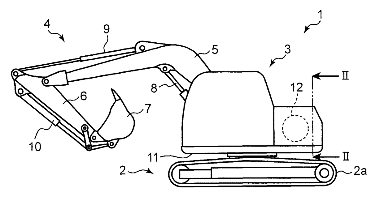
[0023]Referring to FIG. 1, a hydraulic excavator 1 as one example of a construction machine according to a first embodiment of the present invention comprises: a lower traveling body 2 provided with a crawler 2a; an upper slewing body 3 slewably provided on the lower traveling body 2; and an attachment 4 displaceably attached to the upper slewing body 3.

[0024]The attachment 4 comprises: a boom 5 having a base end attached to the upper slewing body 3 rotatably about a horizontal axis upwardly and downwardly; an arm 6 having a base end attached to a distal end of the boom 5 rotatably about a horizontal axis upwardly and downwardly; and a bucket 7 attached to a distal end of the arm 6 rotatably about a horizontal axis.

[0025]The attachment 4 also comprises: a boom cylinder 8 operable to rotatably drive the boom 5 with respect to the upper slewing body 3; an arm cylinder 9 operable to rotatably drive the arm 6 with respect to the boom 5; and a bucket cylinder 10 operable to r...

second embodiment

[0075]In the first embodiment, the lower plate 27 is provided on the engine 12. However, the lower plate 27 may be provided above the slewing frame 11 to support the exhaust aftertreatment device 18 from therebeneath in such a manner that the exhaust aftertreatment device 18 is disposed at a position overlapping the engine in side view.

[0076]For example, the lower plate 27 in a hydraulic excavator according to a second embodiment of the present invention illustrated in FIG. 9 is provided on a holding mechanism 40 provided on the slewing frame 11.

[0077]The holding mechanism 40 comprises a loading plate portion 41, and four legs 42 (in FIG. 9, only two of them are illustrated) provided on the slewing frame 11 to support the loading plate portion 41.

[0078]The lower plate 27 is loaded onto the loading plate portion 41, and fixed to the loading plate portion 41.

[0079]Two of the legs 42 are provided in front of the hydraulic pump 15, and the remaining two legs 42 are provided behind the h...


PUM


Abstract

Provided is a construction machine which is capable of stably support an exhaust aftertreatment device comprising a first treatment section and a second treatment section arranged in one-above-the-other and side-by-side relation. A hydraulic excavator comprises: an exhaust aftertreatment device comprising a first treatment section and a second treatment section which are arranged in one-above-the-other and in side-by-side relation; a lower plate attached to a lower surface of the exhaust aftertreatment device, and provided above a slewing frame to support the exhaust aftertreatment device from therebeneath in such a manner that the exhaust aftertreatment device is disposed at a position overlapping the engine in side view; and a left vertical plate disposed to extend upwardly from a portion of the lower plate located between the exhaust aftertreatment device and the engine, and attached to a lateral surface of the exhaust aftertreatment device.

Description

TECHNICAL FIELD[0001]The present invention relates to a construction machine equipped with an exhaust aftertreatment device for purifying exhaust gas of an engine.BACKGROUND ART[0002]Heretofore, there has been known an exhaust aftertreatment device comprising a first treatment section capable of removing a first component contained in exhaust gas of an engine and a second treatment section capable of removing a second component contained in the exhaust gas.[0003]For example, an exhaust aftertreatment device described in JP 2009-79422A (hereinafter referred to as “Patent Literature 1”) comprises: a first treatment section having a filter (Diesel Particulate Filter) for trapping particulate matter (hereinafter referred to as “PM”) as one example of the first component; and a second treatment section having a catalyst for promoting a selective catalytic reduction (hereinafter referred to as “SCR”) reaction of nitrogen oxides (hereinafter referred to as “NOx”) as one example of the seco...

Claims


Application Information

Patent Timeline
Patent Type & Authority Patents(United States)
IPC IPC(8): F01N13/18E02F9/08F01N3/20
CPCE02F9/0866F01N3/2066F01N13/18
Inventor OGURA, YUTOOZAKI, MASAKAZUKASHIWABARA, TAKESHI
Owner KOBELCO CONSTR MASCH CO LTD
Why Eureka
Try Eureka