
Ribbon transducer

a ribbon transducer and ribbon technology, applied in the direction of transducer details, electrical transducers, electrical apparatus, etc., can solve the problems of limiting the use of transverse corrugation ribbon transducers to higher frequency operation, elongation of ribbon elements, loss of initial installed tension of ribbon elements, etc., to increase the reliability of vibrating ribbon elements, power handling, and the effect of prolonging the useful frequency rang

Inactive Publication Date: 2017-05-30
JAYNE RICHARD ALLEN
View PDF8 Cites 1 Cited by
  • Summary
  • Abstract
  • Description
  • Claims
  • Application Information

AI Technical Summary

Benefits of technology

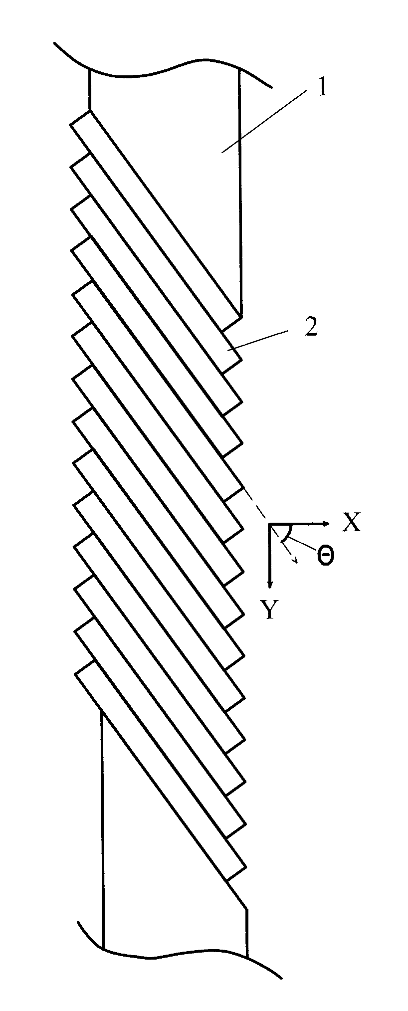
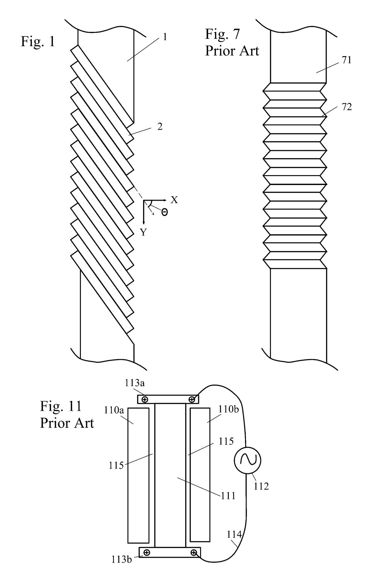
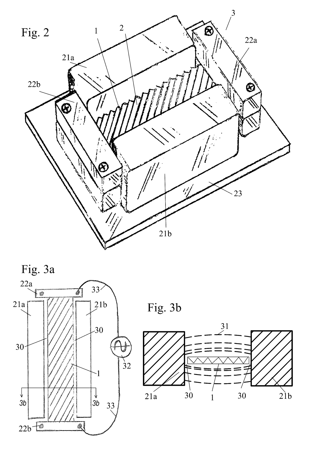
This patent describes a new type of acoustical ribbon transducer that can vibrate more reliably, handle more power, and have a wider range of frequencies it can work with. This is achieved by angling the corrugations in the vibrating ribbon element at an angle between 45 degrees and 75 degrees.

Problems solved by technology

This fact limits practical sized ribbon transducers with transverse corrugations to higher frequency operation where lateral movements are small.
The larger movements and increased lateral forces associated with lower frequency operation easily overwhelms transverse corrugated ribbon elements and can stress the ribbon material past its mechanical yield point resulting in an elongation of the ribbon element and a loss of the ribbon element's initially installed tension.
Also this extreme compliance gives almost no control over standing wave activity at lower frequencies as the transversely corrugated ribbon easily submits to the forces producing this phenomenon resulting in limited power handling and low frequency response irregularities.
As a result of these performance issues, prior art ribbon designs that attempt to reproduce higher sound pressure levels and or lower frequencies have been undesirably large structures, increasing the ribbon's surface area so as to reduce the magnitude of the excursions associated with lower frequency operation.
This fact has limited practical sized free swinging ribbon audio transducers with transverse corrugations to use only at the higher audio frequencies, typically above 1000 hertz or more.
To achieve reliable response below 1000 hertz, the free swinging designs have resorted to undesirably large designs ranging from approximately 2 to 7 feet in length.
This approach does not result in a practical sized loudspeaker as desired by most audio system users.

Method used


Image

  • Ribbon transducer
  • Ribbon transducer
  • Ribbon transducer

Examples


first embodiment

[0053]FIG. 4 shows a perspective view of a fixture for forming a corrugated vibrating ribbon element 1 using a rack 40 and pinion 41 arrangement. FIG. 9 shows a cut-through view of FIG. 4 along the lines 9-9. In this method of forming the ribbon element 1, the flat ribbon element 1 is placed on the rack 40 at the desired angle, and the pinion 41 is rotated about its axis 44. This causes the pinion 41 to travel along the rack 40 as indicated by dash-dot line 45, and the teeth 43 of the pinion 41 bend the ribbon element 1 against the teeth 42 of the rack 40, causing the angled corrugations 2 to form.

second embodiment

[0054]FIG. 5 shows a perspective view of a fixture for forming a corrugated vibrating ribbon element 1, using a pair of pinions 51 and 52. FIG. 10 shows a cut-through view of the embodiment of FIG. 5 along the lines 10-10. In this embodiment, the teeth 55 of pinion 51 interlock with the teeth 56 of pinion 52. As the pinions 51 and 52 rotate about their respective axes 53 and 54, the ribbon element 1 is fed between the pinions at the desired angle. The ribbon element 1 is crimped between the teeth 55 and 56, forming the angled corrugations 2. As the crimps are formed, the ribbon 1 is drawn across the paired pinions 51 and 52, as indicated by the dash-dot arrow 57.

“Composite Ribbon” Embodiment of the Invention

[0055]This embodiment provides a “free swinging” acoustical ribbon transducer with increased vibrating ribbon element reliability, power handling, damping, and extended useful frequency range. This performance is achieved by forming two ribbon elements with angled corrugations as...


PUM


Abstract

A “free swinging” acoustical ribbon transducer with increased vibrating ribbon element reliability, power handling, and extended useful frequency range. This performance is achieved by forming the corrugations in the vibrating ribbon element at an angle in a range of approximately 45 degrees to 75 degrees with respect to the transverse direction, and preferably in a range of 54 degrees to 74 degrees with respect to the transverse direction.

Description

BACKGROUND OF THE INVENTION[0001]Field of the Invention[0002]The invention pertains to the field of acoustic transducers. More particularly, the invention pertains to “free swinging” acoustical ribbon transducers with ribbon elements mechanically terminated only at their ends.[0003]Description of Related Art[0004]A ribbon audio transducer is a type of speaker or microphone, as shown in FIG. 11, in which the sound is generated by a thin strip of metal ribbon 111 which is suspended between two permanent magnets 110a and 110b. A small gap 115 between each of the magnets 110a and 110b and the edges of the ribbon 111 allows the ribbon 111 to vibrate. The ends of the ribbon 111 are held by mounts 113a and 113b which are electrically isolated from each other and electrically connected to the ends of the ribbon 111. An audio source 112 is connected to each of the mounts 113a and 113b by wires 114.[0005]When the transducer is used as a speaker, an alternating current created by signal from t...

Claims


Application Information

Patent Timeline
IPC IPC(8): H04R1/00H04R31/00H04R7/14
CPCH04R7/14H04R31/003H04R9/02
Inventor JAYNE, RICHARD ALLEN
Owner JAYNE RICHARD ALLEN
Learn More