
Footwear

a technology of footwear and straps, applied in the field of footwear, can solve the problems of insufficient effectiveness of counter-supplementing straps, ankle injury, and risk of ankle injuries, and achieve the effects of preventing the occurrence of ankle injuries, improving proprioception, and improving perception

Inactive Publication Date: 2017-06-06
SALOMON SA
View PDF22 Cites 3 Cited by
  • Summary
  • Abstract
  • Description
  • Claims
  • Application Information

AI Technical Summary

Benefits of technology

This patent is about a new shoe design that helps prevent ankle injuries and improves the user's ability to feel the ground. When the foot moves in a way that could cause the ankle to be stretched, the shoe sends a signal to the brain to correct the movement and prevent the injury. This shoe design also enhances the user's awareness of the ground, allowing for better interactions between the shoe and the ground. Overall, this shoe design helps to reduce the risk of ankle injuries and improve the user's sense of touch.

Problems solved by technology

The aforementioned sports in particular involve a risk of ankle injuries, such as sprains, for example.
At the start of a foot inversion movement, the aforementioned action of the counter-supplementing strap does not prevent such movement from amplifying and bringing the foot in a position likely to cause injury to the ankle.
When the ankle twists severely, the counter-supplementing strap is not sufficiently effective to prevent the ankle from twisting.

Method used


Image

  • Footwear
  • Footwear
  • Footwear

Examples


second embodiment

[0068]FIGS. 4 to 6 show a shoe 101 according to the invention. In FIGS. 4 to 6, the elements similar to those of FIGS. 1 to 3 bear the same reference numerals, increased by 100.

[0069]Hereinafter, the elements of the shoe 101 similar to those of the shoe 1 are not described in detail.

[0070]The shoe 101 extends lengthwise between a heel 111 and a front end 112, and widthwise between a lateral side 113 and a medial side 114. It has a longitudinal axis X.

[0071]The shoe 101 comprises an upper 102 designed to surround the user's foot, and a sole assembly 103 including a plurality of soles 131, 132, and 134.

[0072]The upper 102 demarcates a volume V for receiving the foot of a user, and comprises an outer envelope 104 or first envelope.

[0073]Unlike the shoe 1, the shoe 101 comprises no inner liner housed within the outer envelope 104.

[0074]The outer envelope 104 of the upper 102 includes a lateral quarter 141 and a medial quarter 142 affixed by their base to a first lasting board 131, for e...

first embodiment

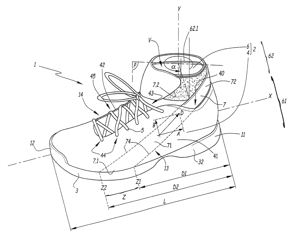
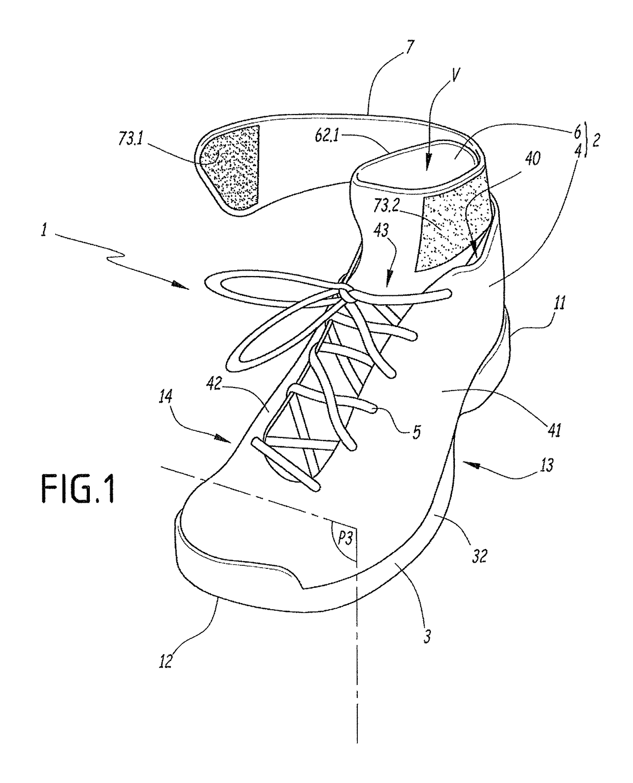
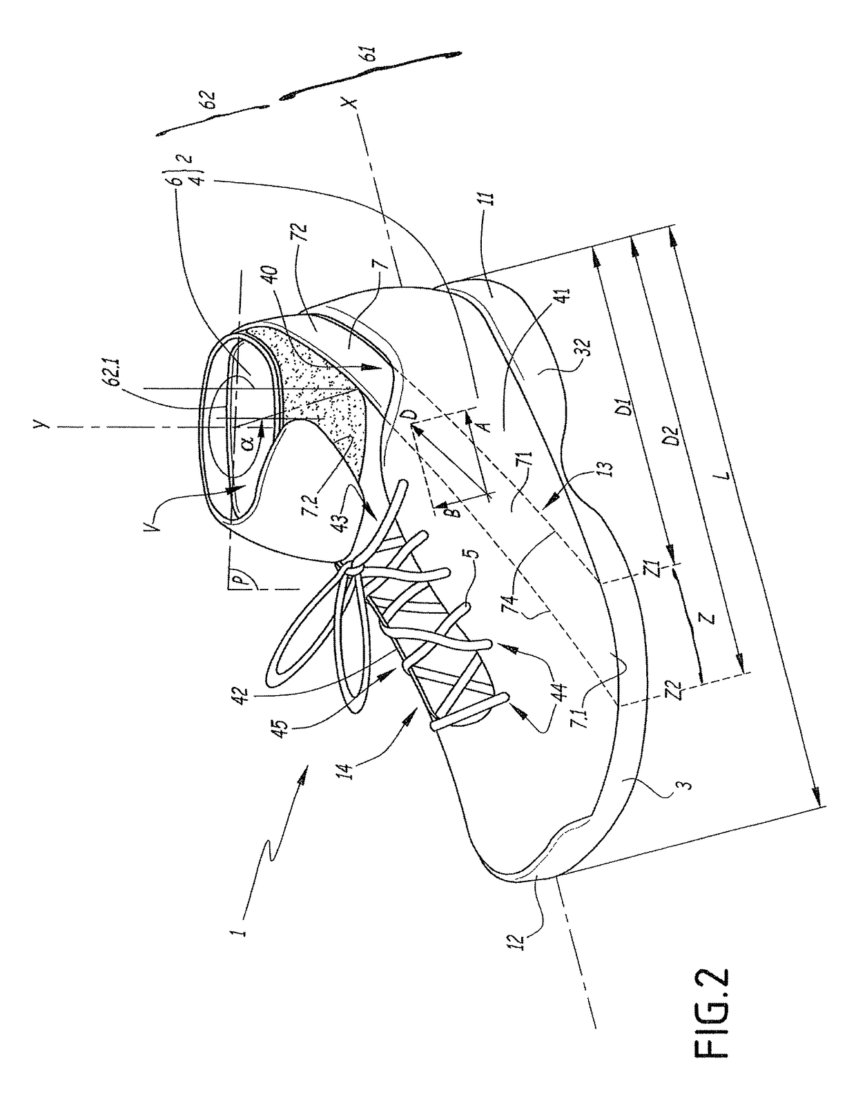
[0081]An information transmission band 107 includes a first end 107.1 attached in the area of the junction between the upper 102 and sole assembly 103, for example by means of stitching or gluing. The first end 107.1 is located on the lateral side 113 of the shoe, in the area of a zone Z1 of the shoe 1 designed to receive the metatarsals of the foot of the user and similar to the zone Z described with reference to the

[0082]The band 107 includes a first portion 171 extending from the first end 107.1 and attached to the lower portion 161 of the upper 102, for example by means of stitches 174 extending along the first portion, in the area of the anchoring zone Z.

[0083]The band 107 includes a second portion 172 extending the first portion 171 and designed to wrap around the upper portion 162, so as to tighten the upper portion 162 and the lower leg of the user. The second portion 172 ends with a free end 107.2, opposite the first end 107.1.

[0084]The inner surface of the second portion 1...


PUM


Abstract

A shoe including a sole assembly; an upper including a first envelope that includes a lower portion designed to surround the foot of a user; and an upper portion designed to surround the ankle or the ankle and a portion of the lower leg of the user; and an information transmission band that includes a first portion affixed to the sole assembly and / or the lower portion of the first envelope by a connection device, such as stitches; and a second portion designed to wrap around the upper portion of the first envelope, extending the first portion and including a first fastening device that cooperates with a second fastening device affixed to the upper portion of the first envelope.

Description

CROSS-REFERENCE TO RELATED APPLICATION[0001]This application is based upon French Patent Application No. 13 / 02298, filed Oct. 3, 2013, the disclosure of which is hereby incorporated by reference thereto in its entirety, and the priority of which is claimed under 35 U.S.C. §119.BACKGROUND[0002]1. Field of the Invention[0003]The invention relates to an article of footwear, such as a shoe, in particular a sports shoe.[0004]A shoe of the aforementioned type may be used in particular for sports such as tennis, badminton, volleyball, soccer, baseball, basketball, or boxing, as well as for other activities. The aforementioned sports in particular involve a risk of ankle injuries, such as sprains, for example.[0005]2. Background Information[0006]U.S. Pat. No. 8,302,329-B1 discloses a basketball shoe equipped with a counter-supplementing strap anchored on the lateral side of the shoe and surrounding the rear portion of the shoe. This strap is attached to the front of the foot with laces. The...

Claims


Application Information

Patent Timeline
Patent Type & Authority Patents(United States)
IPC IPC(8): A43B3/00A43B5/02A43B1/00A43B5/00A43B5/10A43B7/20A43B19/00A43B7/14
CPCA43B3/0005A43B1/0081A43B5/00A43B5/02A43B5/10A43B7/14A43B7/20A43B19/00A43B3/34
Inventor NORMAND, JOSEPH
Owner SALOMON SA
Learn More