Piston ring with a periodically varying groove

a technology of rotating grooves and piston rings, applied in the field of piston rings, can solve the problems of short distribution of lubricant and short supply of lubricant, and great challenges in ensuring the quality of lubrication, and achieve the effect of uniform distribution and reduction of the amount of lubricant needed

Active Publication Date: 2017-06-06
FEDERAL MOGUL BURSCHEID
View PDF14 Cites 1 Cited by
  • Summary
  • Abstract
  • Description
  • Claims
  • Application Information

AI Technical Summary

Benefits of technology

[0013]The running face of the piston ring formed in this manner can receive lubricant in a cavity that is formed by the groove and a counter running face. The periodically varying depth course and the periodically varying width course of the groove causes hydrodynamic pressures to build up or arise (in particular varying periodically with the depth course and width course) in the circumferential directi...

Problems solved by technology

If one considers that modern, large-volume two-stroke ship engines are operated at a speed of approximately 50 rpm to 250 rpm with a stroke of up to 2500 mm, the time s...

Method used


Image

  • Piston ring with a periodically varying groove
  • Piston ring with a periodically varying groove
  • Piston ring with a periodically varying groove

Examples


Embodiment Construction

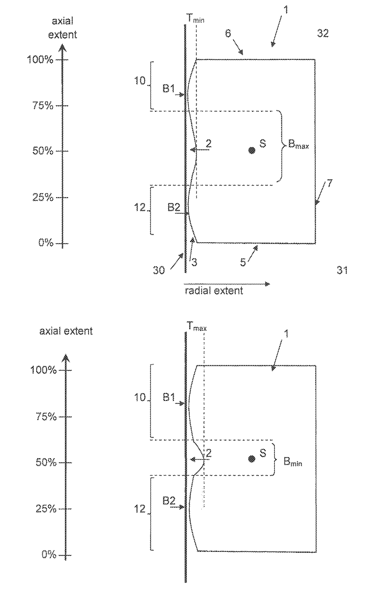
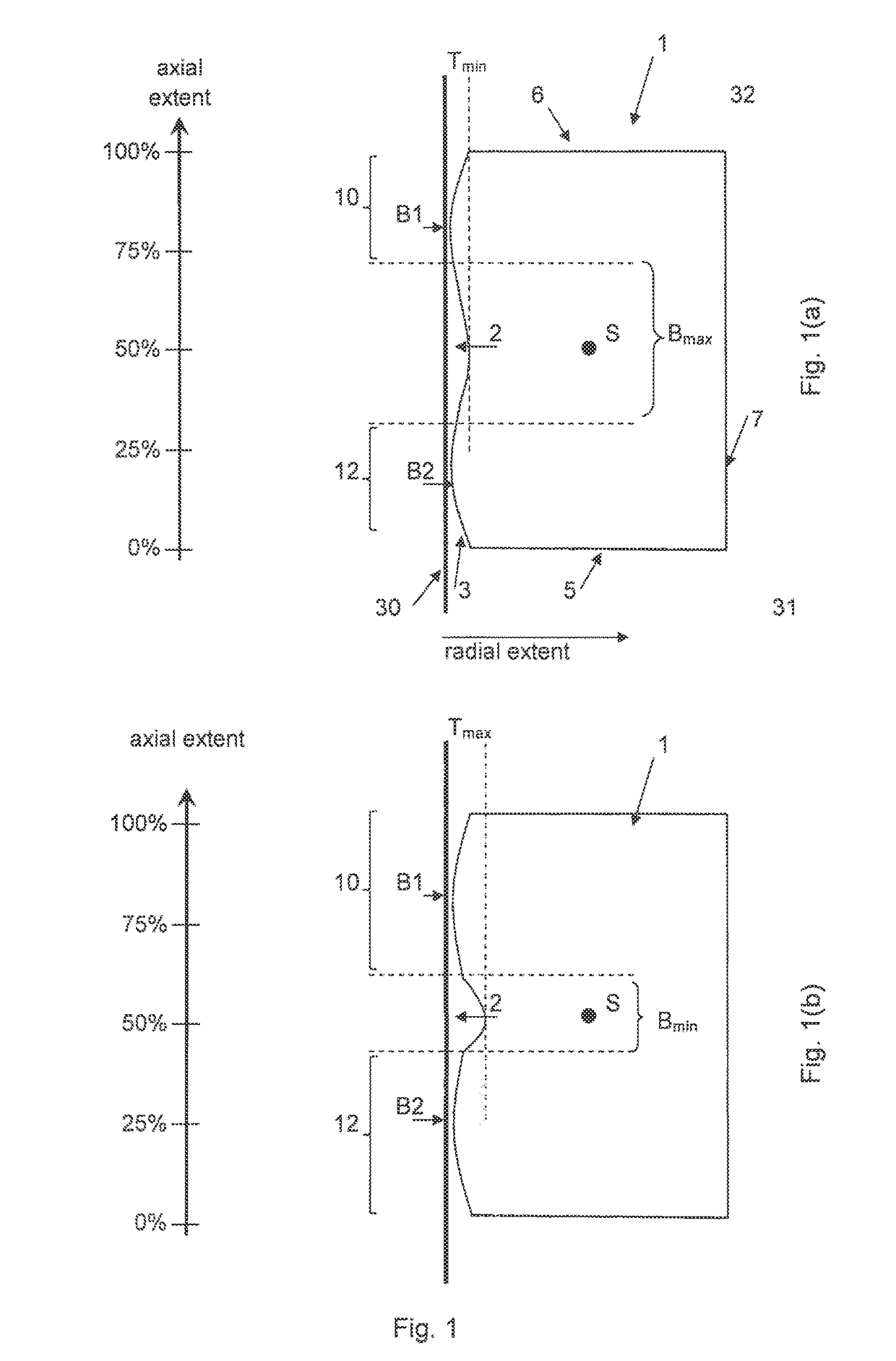
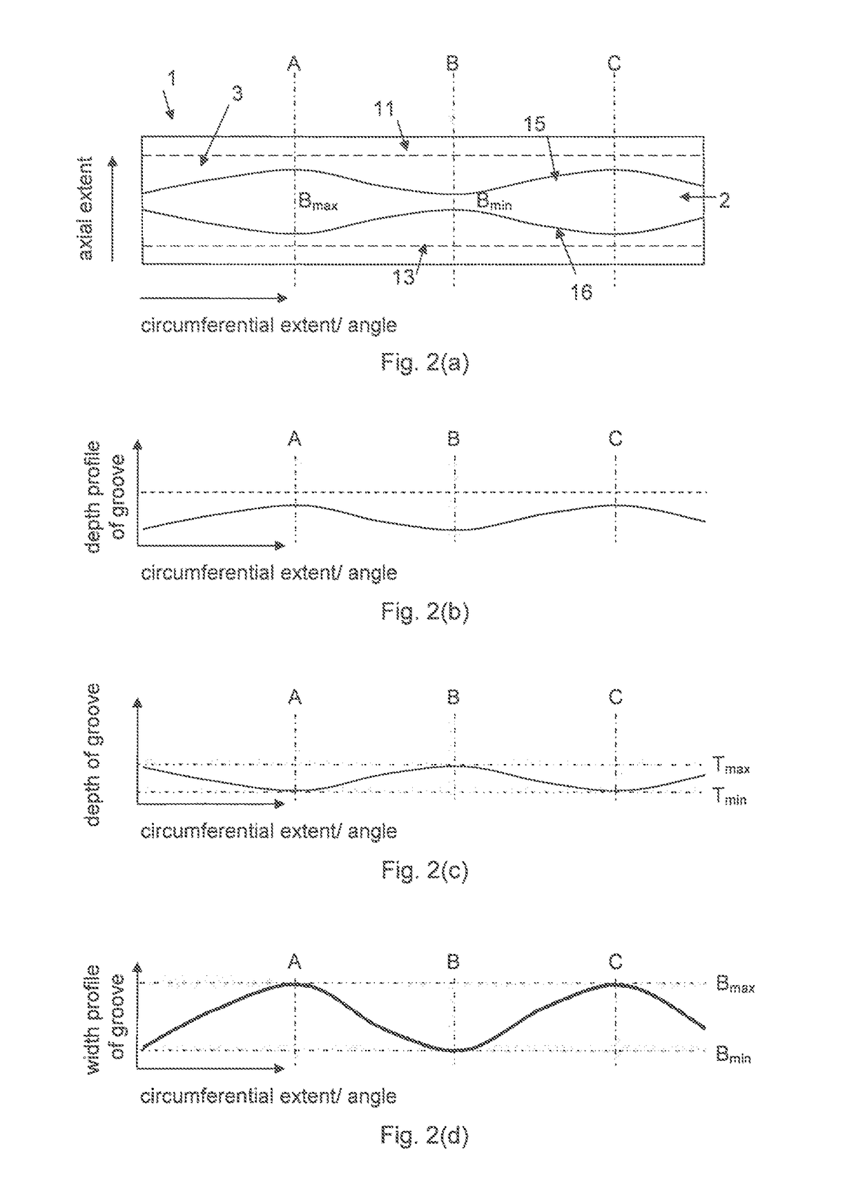
[0024]FIG. 1 shows two (radial) cross sections, which are spaced apart from each other in the circumferential direction, through a piston ring 1 according to the invention. The piston ring 1 according to the invention, which is shown in FIG. 1 and preferably acts as a compression and oil control ring at the same time, with a groove has a cut-out or groove 2 on its outer, profiled side that faces away from the combustion chamber, i.e. on the profiled running face 3 of the piston ring 1, said groove being illustrated schematically in FIG. 1. The piston ring 1 also has a flank 5 that faces the combustion chamber 31, a flank 6 that faces the oil chamber 32, and an inner circumferential face 7.

[0025]It should be noted that, although the description above and below relates to the use of the piston ring 1 according to the invention for a piston in an internal combustion engine, in particular in a two-stroke internal combustion engine, it is immediately clear to a person skilled in the art ...


PUM


Abstract

A piston ring having an outer running face, two flanks and an inner circumferential face is provided, the running face of which has profiling with a groove. The groove is arranged between two running face sections in relation to the cross section of the piston ring. The two running face sections are spaced apart from each other and substantially convexly curved and each have an apex. The groove has a periodically varying depth and a periodically varying width, and the number of periods of the course of the depth and the number of periods of the course of the width are equal.

Description

BACKGROUND OF THE INVENTION[0001]1. Technical Field[0002]The present invention relates to a piston ring for an internal combustion engine or for a compressor, in particular a piston ring having a groove that is arranged on the running face and has a periodically varying width and a varying, variable depth in the circumferential direction.[0003]2. Related Art[0004]Modern, large-volume engines for ships are still two-stroke diesel engines, since this type of engine can be designed in such a manner that the speed thereof is typically in a range from approximately 50 rpm to 250 rpm (typically less than 100 rpm) and the power thereof can reach up to approximately 100 MW, depending on the number of cylinders. Such large-volume, slow-running two-stroke ship engines preferably act directly on the drive shaft(s) of the propeller(s), since a reduction gear to reduce the rotation speed can be omitted owing to the speed of said engines.[0005]Such large-volume two-stroke engines typically have t...

Claims


Application Information

Patent Timeline
IPC IPC(8): F16J9/20
CPCF16J9/20
Inventor MITTLER, RICHARDNATHEM, FRANK
Owner FEDERAL MOGUL BURSCHEID
Why Eureka
Try Eureka