Valve box

a valve box and valve body technology, applied in the field of valve boxes, can solve the problems of not being suitable for the not much suitable for detection of water distribution pipes, and high detection costs

Active Publication Date: 2017-06-06
SOC PLYMOUTH FR
View PDF14 Cites 3 Cited by
  • Summary
  • Abstract
  • Description
  • Claims
  • Application Information

AI Technical Summary

Benefits of technology

[0012]The technical problem underlying the invention is therefore of providing a valve box which is of simple and economical structure, and which allows an easy and rapid detection of a buried pipe, such as a water distribution pipe.
[0014]The structure of the valve box according to the invention allows to inject an electrical signal in an electrically conductive wire associated with a pipe simply by connecting a current generator directly to the body of the valve box. The result is an easy localization of the pipe associated with the electrically conductive wire by using an electromagnetic detector arranged to detect the electromagnetic field created by the alternating current flowing in the electrically conductive wire.
[0015]Moreover, the localization of a pipe using a valve box according to the invention is economical, since it does not require the installation of a large number of connection casings in addition to the installation of the valve boxes.
[0028]The connection member comprises for example at least one support part and at least one clamping part intended to clamp the corresponding electrically conductive wire against the support part. Each clamping part is advantageously formed by an elastically deformable clamping tongue. These arrangements allow a rapid fixing of an electrically conductive wire, and this without requiring the use of a tool.

Problems solved by technology

Such a detection method proves to be expensive since it requires the installation of a large number of connection casings along the pipe to be detected, each casing being for example disposed either within a technical gallery, or on a non-buried terminal.
Moreover, such a method is not much suitable for the detection of water distribution pipes, since it is difficult to install the connection casings in the vicinity of water systems.
Such a detection method is not suitable for the detection of water pipes, since a large part of the water pipes used are not electrically conductive on the one hand, and the water pipes are mostly inaccessible from the surface on the other hand.
Thus, an electrical signal injected into the water pipe could not propagate beyond the first elastomer seal, and therefore would make the water pipe monitoring impossible.

Method used


Image

  • Valve box
  • Valve box
  • Valve box

Examples


Embodiment Construction

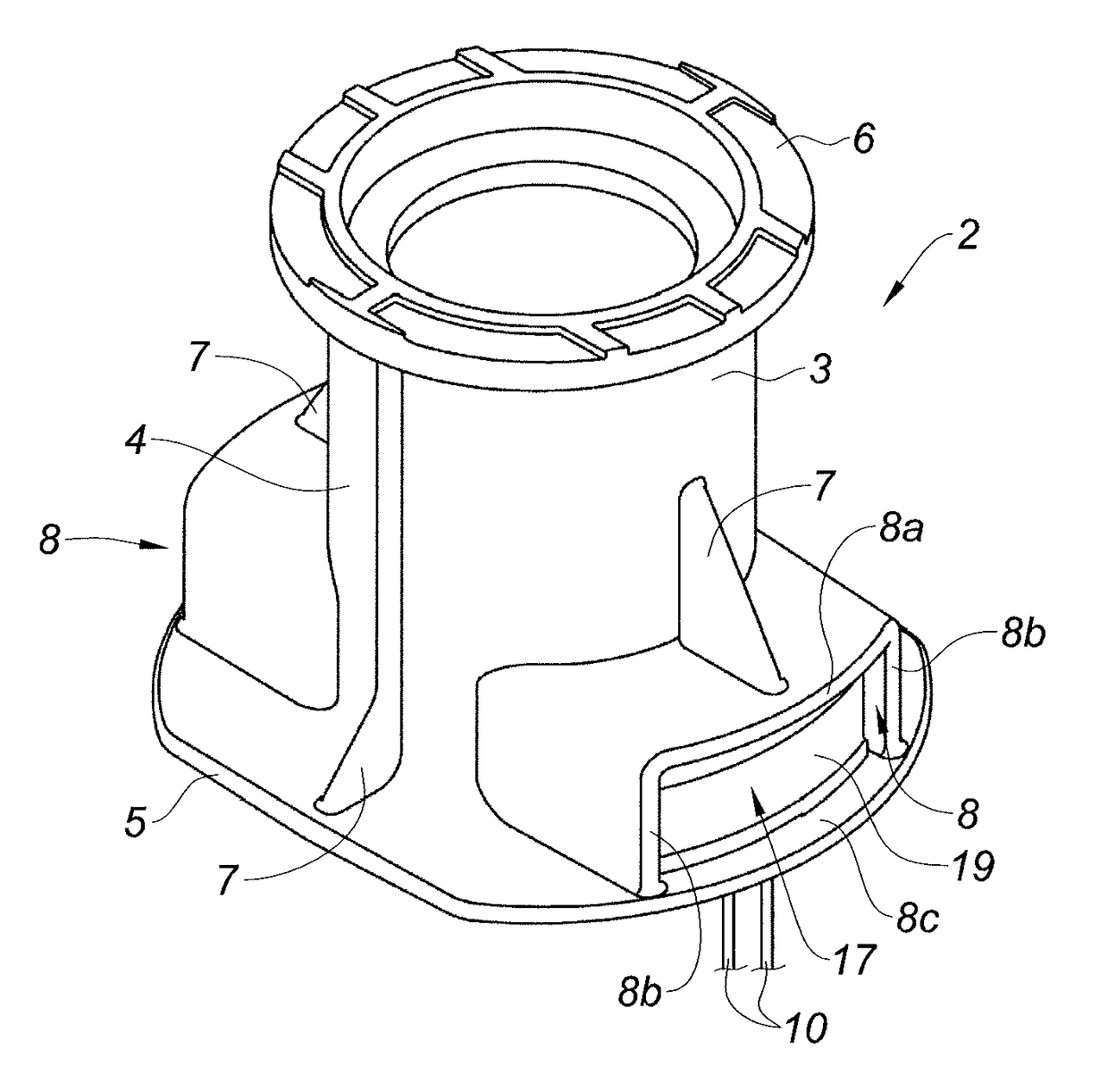
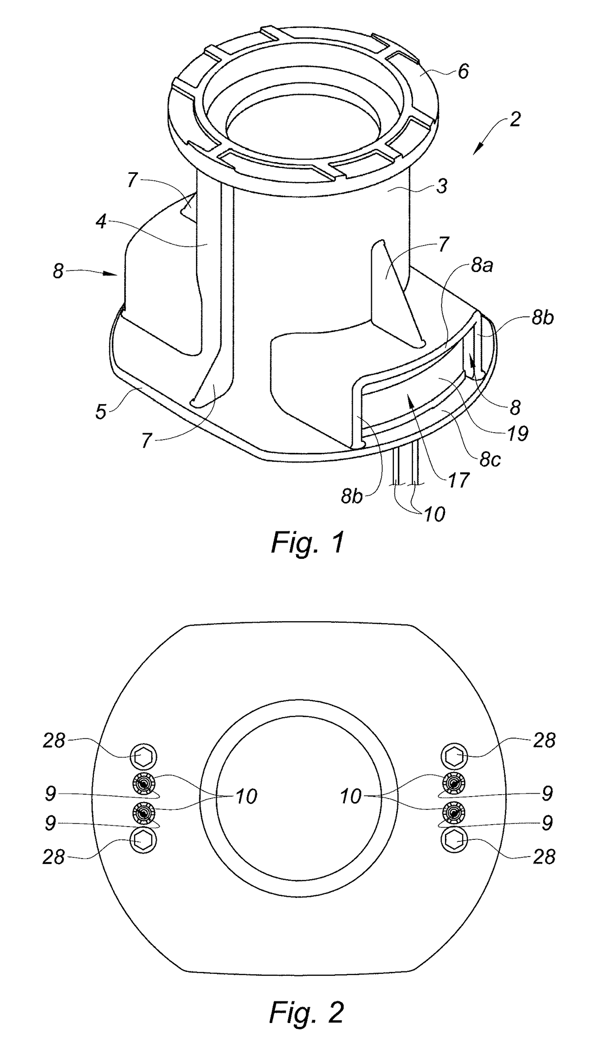
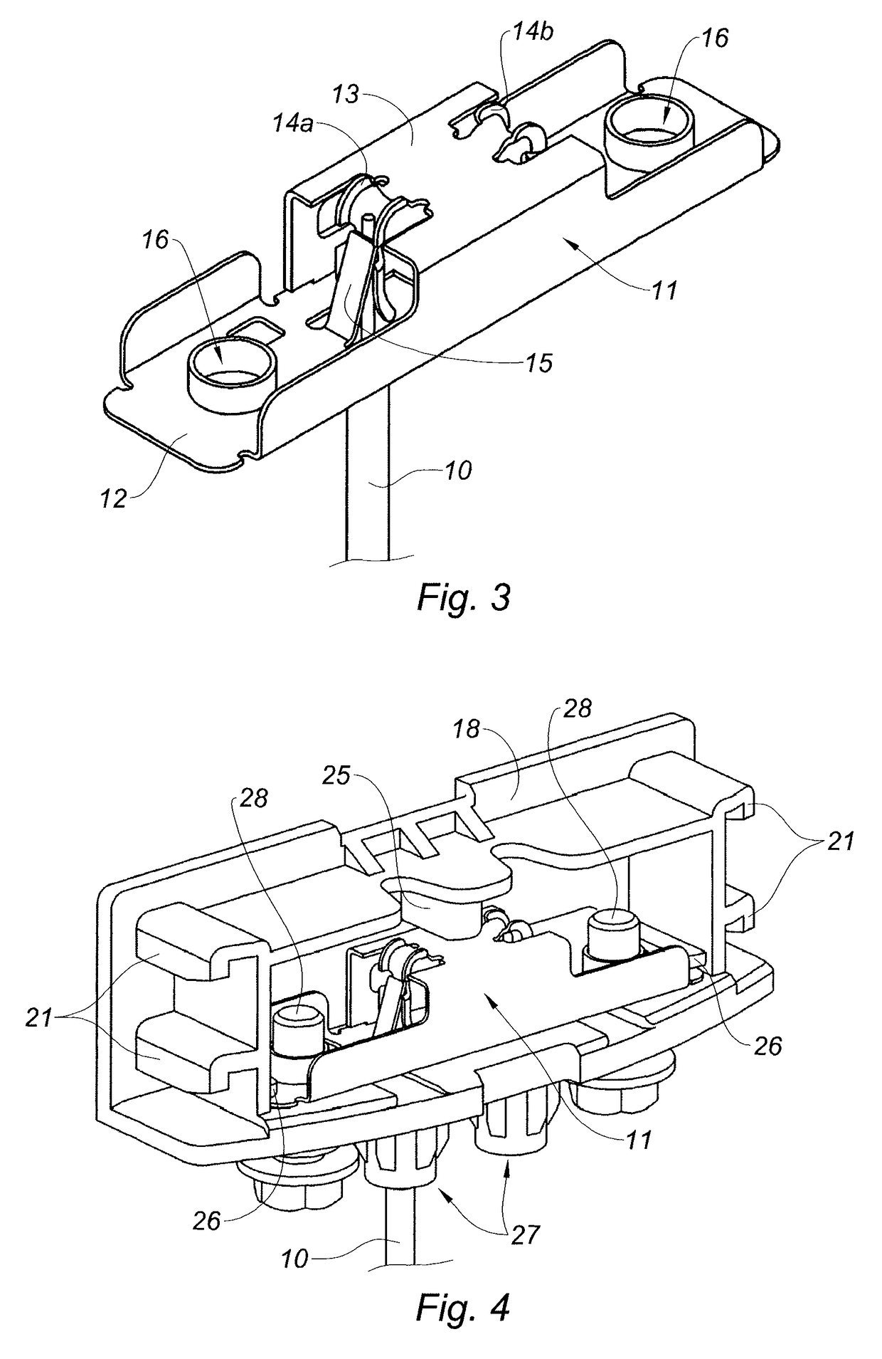
[0055]FIGS. 1 to 4 represent a valve box 2 intended to be located at ground level so as to allow access, using a suitable key, to the operating member of a valve of a buried pipe, such as a water distribution pipe.

[0056]The valve box 2 includes a metal body 3, preferably made of cast-iron, having a generally tubular shape. The body 3 comprises a tubular part 4, a base 5 formed by a lower peripheral flange extending radially from the lower edge of the tubular part 4, and an upper peripheral flange 6 extending radially from the upper edge of the tubular part 4. The upper peripheral flange 6 is intended to receive a closing buffer (not shown in the figures) and to be located at the level of the roadway. The tubular part 4 is intended for the passage of an actuating key of the operating member of the corresponding valve.

[0057]The body 3 comprises longitudinal wings 7 intended to rotationally immobilize the body 3 in cooperation with the ground. The longitudinal wings 7 are regularly dis...


PUM


Abstract

This hydrant (2) comprises an electrically conductive body (3) having a generally tubular shape and intended for being fixed in the floor flush with a valve mounted on a pipe, for example a water distribution pipe. The hydrant comprises connection means suitable for connecting at least one electrically conductive wire (10) extending along the pipe, said connection means being connected to the body (3) such that electric continuity is maintained between the body (3) and each electrically conductive wire (10) during use.

Description

TECHNICAL FIELD[0001]The present invention relates to a valve box, and a method for detecting a buried pipe using a valve box.BACKGROUND[0002]A valve box is a device intended to be located at ground level so as to allow the access, using an appropriate key, to the operating member of a valve of a buried pipe, such as a water distribution pipe.[0003]It is important for saving time and costs, but also for improved safety, to be able to detect the presence of such a pipe, and to localize it accurately, without digging the ground, nor destroying building, on the occasion of the subsequent works.[0004]Several methods can be used to perform the detection of buried pipes.[0005]The detection via an electromagnetic channel is the most commonly used method. This electromagnetic detection can be performed using electromagnetic detectors based on the active detection of an electromagnetic signal.[0006]A first known method of active detection comprises injecting, using a current generator, an el...

Claims


Application Information

Patent Timeline
Patent Type & Authority Patents(United States)
IPC IPC(8): G01V3/08E03B9/04E03B9/08F16L1/11H01R4/48
CPCG01V3/08E03B9/04E03B9/08F16L1/11H01R4/4818Y10T137/5456H01R4/48185
Inventor SAAD, MOUNIRARNAUD, DANIEL
Owner SOC PLYMOUTH FR
Why Eureka
Try Eureka