Electrical receptacle connector

a technology of electric receptacles and connectors, which is applied in the direction of coupling device connections, coupling protective earth/shielding arrangements, and two-part coupling devices. it can solve the problems of easy generation of signal interference between the signal terminals, the inability to improve the existing connector, and the small distance between the upper and lower high-speed signal terminals

Active Publication Date: 2017-06-06
ADVANCED CONNECTEK INC
View PDF10 Cites 3 Cited by
  • Summary
  • Abstract
  • Description
  • Claims
  • Application Information

AI Technical Summary

Benefits of technology

[0005]However, when the front of each of the lower receptacle terminals is bent, the distance between each of the upper high-speed signal terminals and the corresponding lower high-speed signal terminal is quite small, and signal interference between the signal terminals may be generated easily.
[0016]Based on the above, the first through holes formed on the tongue portion correspond to the extending portions between the second high-speed signal terminals, the power terminals, and the ground terminals of the second receptacle terminals. Pressing fixtures can be inserted into the first through holes to cut away the extending portions and form and remain the cut portions (i.e. cut surfaces). The extending portions between the second high-speed signal terminals, the power terminals, and the ground terminals of the second receptacle terminals allows the second receptacle terminals to be positioned so as to be assembled with the second portion properly. Accordingly, each pair of the first high-speed signal terminals is spaced from the corresponding pair of the second high-speed signal terminals by a uniform interval, and the signal interference problem between the first high-speed signal terminals and the second high-speed signal terminals can be prevented and improved. Hence, problems found in the conventional can be improved.
[0017]In addition, the manufacturing of the assembly of the insulated housing and the receptacle terminals has two times of insert-molding procedures, in a first time insert-molded procedure, the first receptacle terminals are integrated with the first portion, and the second receptacle terminals are integrated with the second portion. Next, in a second time insert-molded procedure, the filling members are formed in the first through holes to cover the body portion of each of the second high-speed signal terminals, the body portion of each of the power terminals, and the body portion of each of the ground terminals. The filling members are filled in the first through holes to separate each pair of the first high-speed signal terminals from the corresponding pair of the second high-speed signal terminals. As a result, the first high-speed signal terminals and the second high-speed signal terminals can be positioned properly. In addition, the filling members improves the structural strength of the tongue portion, and the filling members prevent the power terminals and the ground terminals exposed out of the first through holes from being connected electrically with each other. It is understood that when water moist is attached to the surfaces of the second receptacle terminals, short circuit problem may occur; in other words, the filling members can reduce the possibility of the short circuit problem.

Problems solved by technology

However, when the front of each of the lower receptacle terminals is bent, the distance between each of the upper high-speed signal terminals and the corresponding lower high-speed signal terminal is quite small, and signal interference between the signal terminals may be generated easily.
Accordingly, how to improve the existing connector becomes an issue.

Method used


Image

  • Electrical receptacle connector
  • Electrical receptacle connector
  • Electrical receptacle connector

Examples


first embodiment

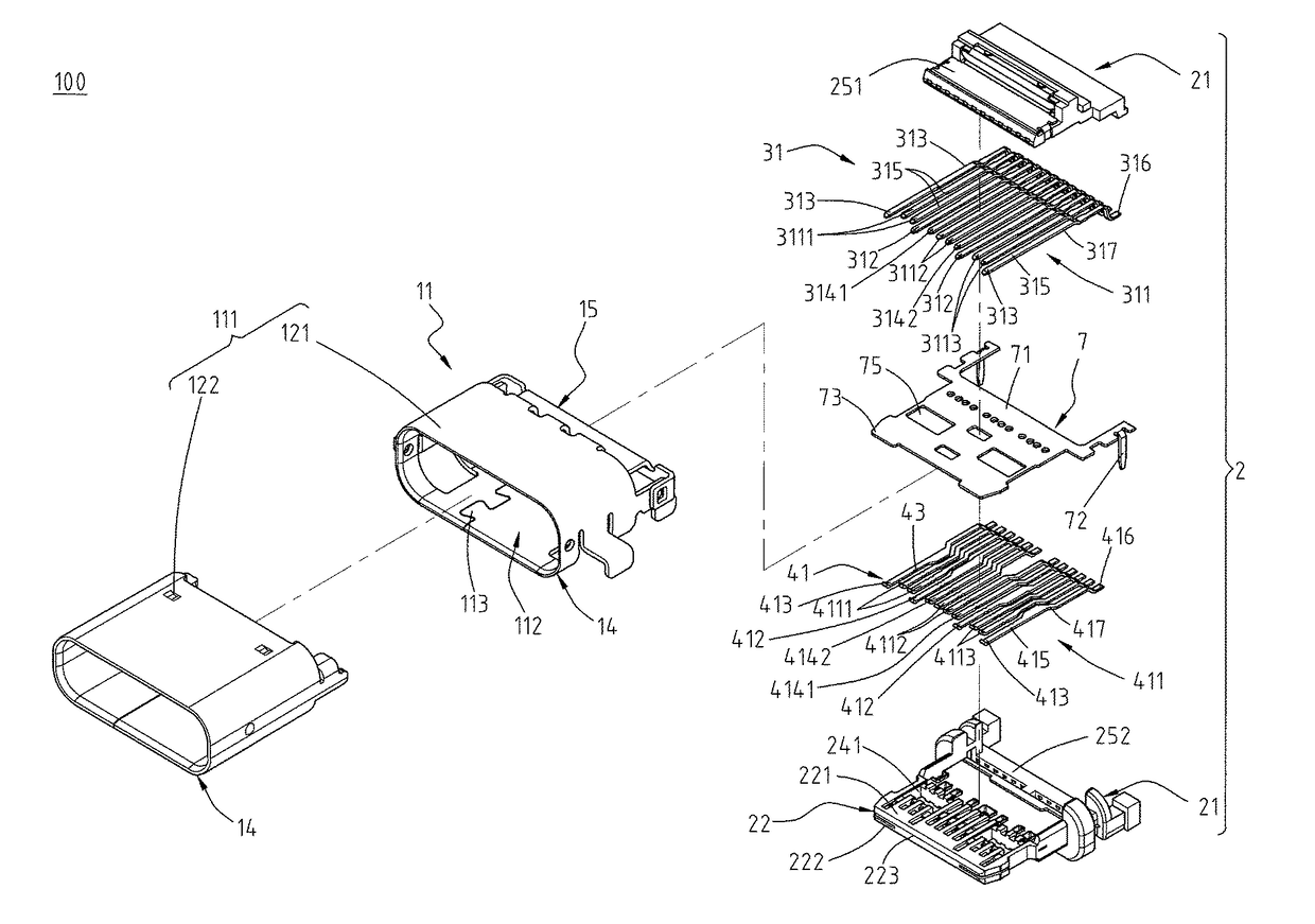
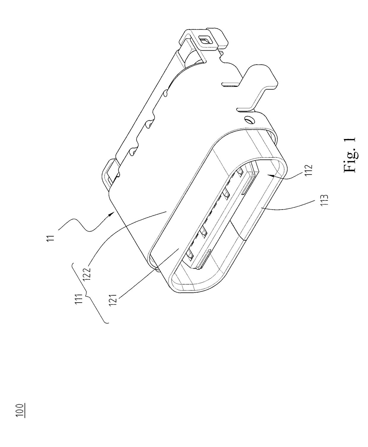
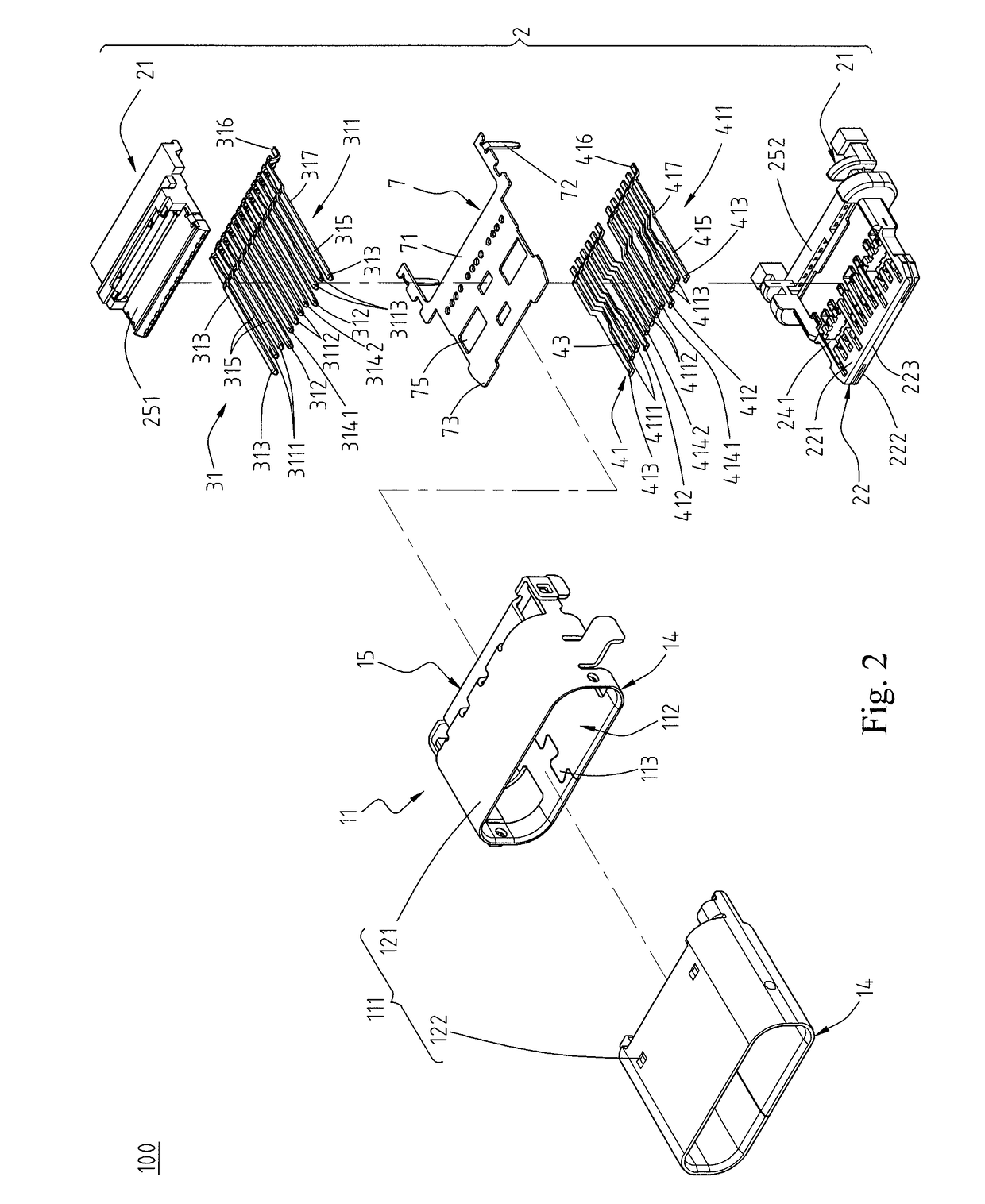
[0037]Please refer to FIGS. 1 to 4, which illustrate an electrical receptacle connector 100 of the instant disclosure. FIG. 1 illustrates a perspective view of an electrical receptacle connector 100. FIG. 2 illustrates an exploded view of the electrical receptacle connector 100. FIG. 3 illustrates a partial exploded view showing the assembly of first receptacle terminals 31 and a first portion 251 and the assembly of second receptacle terminals 41 and a second portion 252. FIG. 4 illustrates a lateral sectional view of the electrical receptacle connector 100. In this embodiment, the electrical receptacle connector 100 can provide a reversible or dual orientation USB Type-C connector interface and pin assignments, i.e., a USB Type-C receptacle connector. In this embodiment, the electrical receptacle connector 100 comprises a metallic shell 11, an insulated housing 2, a plurality of first receptacle terminals 31, a plurality of second receptacle terminals 41, and a plurality of fillin...

second embodiment

[0065]Please refer to FIGS. 10 to 12. In the second embodiment, the insulated housing 2 further comprises a second through hole 242 formed at a middle portion of the rear of the tongue portion 22. In other words, the second through hole 242 is formed at a middle portion of the rear of the tongue portion 22 of the second portion 252 and adjacent to the base portion 21, but embodiments are not limited thereto. Alternatively, the second through hole 242 may be formed at a middle portion of the front of the tongue portion 22. The structure and the function of the second through hole 242 are similar to that of the first through hole 241. In addition, the body portions 417 of the pair of the second low-speed signal terminals 4112 correspond to the second through hole 242 at the middle portion of the rear of the tongue portion 22. In addition, the pair of the second low-speed signal terminals 4112 and their left supplement terminal 4142 are integrated with each other by the extending porti...

third embodiment

[0068]Please refer to FIGS. 14 to 16. In the third embodiment, each of the second receptacle terminals 41 further comprises a turning portion 461 and a lengthened portion 462. The turning portion 461 is extending upward from the front of the flat contact portion 415 and bending toward the tongue portion 22. The lengthened portion 462 is extending from the top of the turning portion 461 and extending toward the front lateral surface 223 of the tongue portion 22. The electrical receptacle connector 100 further comprises a strip or belting 47 connecting to the second receptacle terminals 41. The second receptacle terminals 41 and the strip or belting 47 are integrated with each other as a whole. In other words, the lengthened portions 462 are extending to the strip or belting 47, and the lengthened portions 462 are integrated with the strip or belting 47.

[0069]Please refer to FIG. 2 and FIGS. 14 to 16. In this embodiment, the turning portion 461 and the lengthened portion 462 may be ex...


PUM


Abstract

An electrical receptacle connector includes a metallic shell, an insulated housing, a plurality of first receptacle terminals, and a plurality of second receptacle terminals. The insulated housing is received in the receiving cavity. The insulated housing includes a tongue portion and a plurality of first through holes formed on the tongue portion. The first receptacle terminals are held in the tongue portion. The second receptacle terminals are held in the tongue portion. The second receptacle terminals include a plurality of cut portions corresponding to the first through holes.

Description

CROSS-REFERENCES TO RELATED APPLICATIONS[0001]This non-provisional application claims priority under 35 U.S.C. §119(a) on Patent Application No. 201510279849.1 filed in China, P.R.C. on 2015 May 28, the entire contents of which are hereby incorporated by reference.FIELD OF THE INVENTION[0002]The instant disclosure relates to an electrical connector, and more particular to an electrical receptacle connector.BACKGROUND[0003]Generally, Universal Serial Bus (USB) is a serial bus standard to the PC architecture with a focus on computer interface, consumer and productivity applications. The existing Universal Serial Bus (USB) interconnects have the attributes of plug-and-play and ease of use by end users. Now, as technology innovation marches forward, new kinds of devices, media formats and large inexpensive storage are converging. They require significantly more bus bandwidth to maintain the interactive experience that users have come to expect. In addition, the demand of a higher perfor...

Claims


Application Information

Patent Timeline
Patent Type & Authority Patents(United States)
IPC IPC(8): H01R13/648H01R13/6585H01R13/405H01R24/60H01R24/78H01R43/24H01R24/00H01R107/00
CPCH01R13/405H01R13/6585H01R24/60H01R23/02H01R24/78H01R43/24H01R2107/00H01R24/00
Inventor TSAI, YU-LUNHOU, PIN-YUANLIAO, CHUNG-FUKAO, YA-FENXIANG, DONGCHEN, LONG-FEI
Owner ADVANCED CONNECTEK INC
Why Eureka
Try Eureka