
Noise canceller device

a noise canceller and noise technology, applied in sustainable communication technology, climate sustainability, high-level techniques, etc., can solve the problems of deterioration of communication environment, difficult to remove interference signals by filters or the like, and interference signals that cannot be accurately and stably removed, etc., to achieve the effect of reducing interference signals, reducing interference, and improving accuracy

Active Publication Date: 2019-10-17
KOKUSA ELECTRIC CO LTD
View PDF0 Cites 1 Cited by
  • Summary
  • Abstract
  • Description
  • Claims
  • Application Information

AI Technical Summary

Benefits of technology

The noise canceller device described in this patent is designed to remove interference signals in an environment where both the desired signal and the interference signal are present. It includes multiple interference signal adjustment units that adjust the delay, phase, and amplitude of the interference signal received by a second antenna. Adders and average power calculation units are used to determine the optimal values for these adjustments. An optimal condition search unit is used to determine the minimum average power as the optimal condition for the interference signal adjustment. An optimal interference signal adjustment unit is used to adjust the signal received by the second antenna based on the optimal conditions. A cancellation unit is used to subtract the output of the optimal interference signal adjustment unit from the signal received by the first antenna. The device can accurately and stably remove interference signals in an environment where they are present and the desired signal is intermittent.

Problems solved by technology

In a conventional wireless communication system, a desired signal interferes with a signal of another system, which may result in deterioration of a communication environment.
At that time, if radio waves leak from the reception facilities, interference may occur in a band of a cellular phone system.
A signal band of satellite broadcasting which becomes an interference signal is wider than the band of the cellular phone which is a desired signal and, thus, it is difficult to remove the interference signal by a filter or the like.
However, when a replica of the interference signal cannot be prepared, it is difficult to remove only the interference signal.
When the interference signal cannot be removed, the communication quality of a cellular phone which is a desired signal deteriorates.
However, the conventional noise canceller device does not sufficiently consider the accurate and stable removal of the interference signals in an environment where the interference signal is steadily present and the desired signal is not steadily present.

Method used


Image

  • Noise canceller device
  • Noise canceller device
  • Noise canceller device

Examples


first embodiment

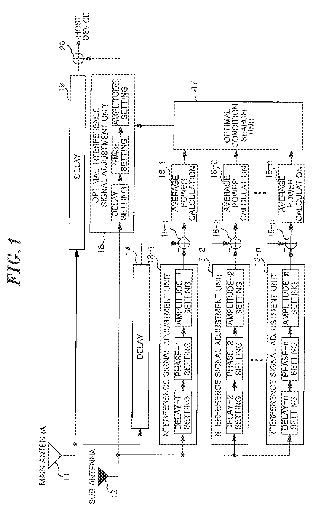
[0035]As shown in FIG. 1, the noise canceller device (first noise canceller device) according to the present invention includes: a main antenna 11, a sub antenna 12, a plurality of interference signal adjustment units 13 (13-1 to 13-n), a delay unit 14, a plurality of adders 15 (15-1 to 15-n), a plurality of average power calculation units 16 (16-1 to 16-n), an optimal condition search unit 17, an optimal interference signal adjustment unit 18, a delay unit 19, and a cancellation unit 20.

[0036]The cancellation unit 20 is connected to a host device that performs information processing of a signal.

[0037]The respective components of the first noise canceller device will be described.

[0038](Main Antenna 11)

[0039]The main antenna 11 receives a desired signal, specifically a wireless signal of a cellular phone. However, an interference signal (leakage signal from a BS antenna) of another system is mixed in the main antenna 11. The main antenna 11 corresponds to a first antenna to be descr...

second embodiment

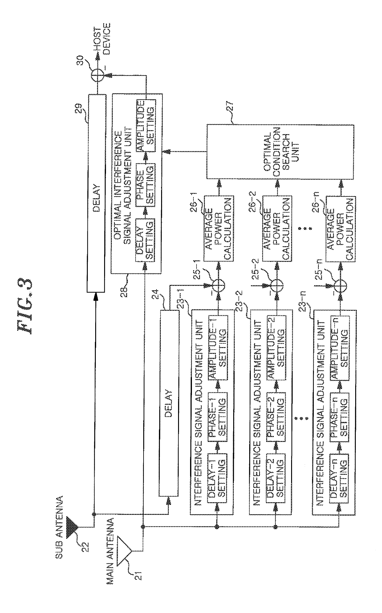
[0096]Next, a noise canceller device (second noise canceller device) according to the present invention will be described with reference to FIG. 3. FIG. 3 is a block diagram showing a configuration of the second noise canceller device.

[0097]In the above-described first noise canceller device, the delay, the phase and the amplitude of the signal received by the sub antenna 12 are adjusted. However, in the second noise canceller device, the interference signal included in the signal received by the main antenna 11 is removed by adjusting the signal received by the main antenna such that the components of the interference signal included in the signal received by the main antenna 11 become close to those of the interference signal received by the sub antenna 12.

[0098]As shown in FIG. 3, the components of the second noise canceller device are the same as those of the first noise canceller device shown in FIG. 1 except that the signal received by the main antenna 21 is divided into a plu...

third embodiment

[0108]Next, a noise canceller device (third noise canceller device) according to the present invention will be described with reference to FIG. 4. FIG. 4 is a block diagram schematically showing the third noise canceller device.

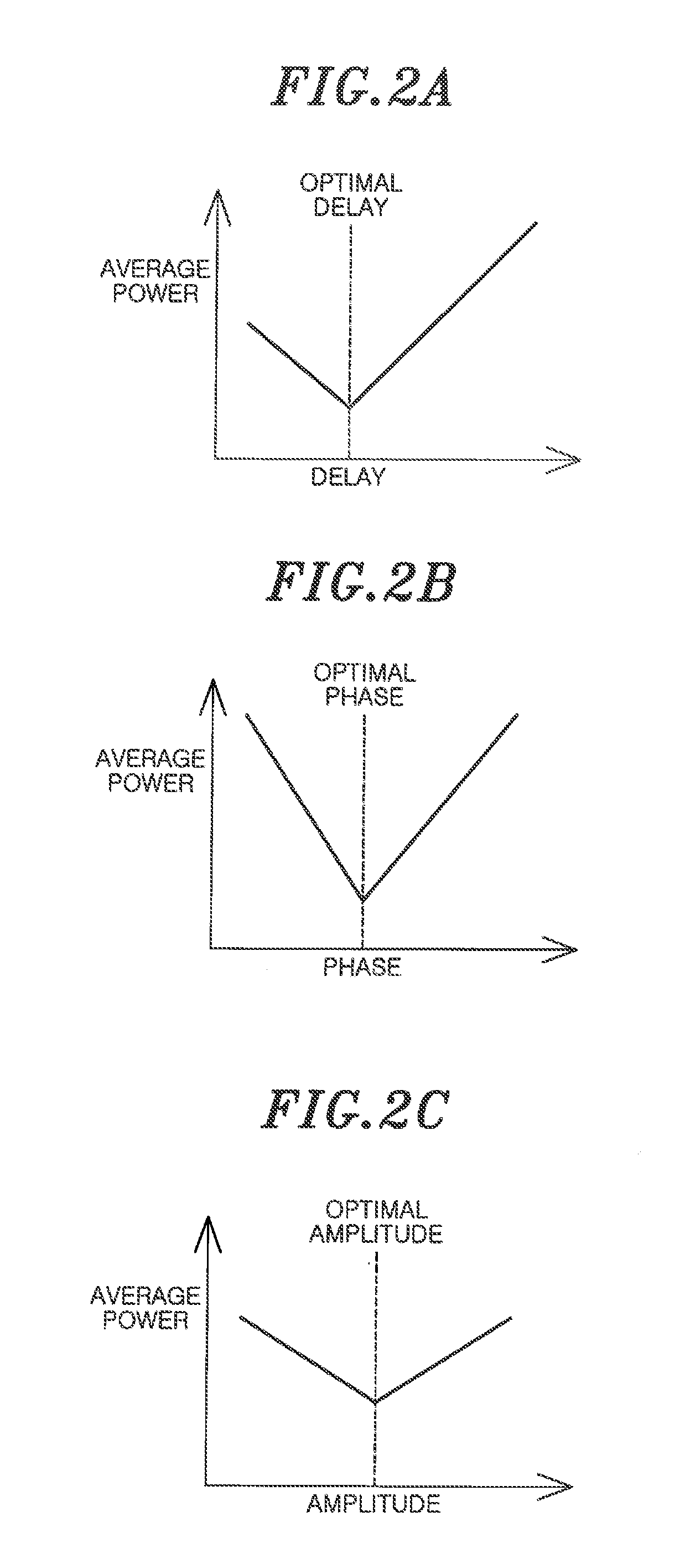
[0109]The first and the second noise canceller device adjust the parameters of the delay, the phase and the amplitude, calculate the average power, and obtain the optimal value. However, the third noise canceller device sequentially searches the optimal values of the delay, the phase and the amplitude.

[0110]As shown in FIG. 4, the third noise canceller device includes the main antenna 31, the sub antenna 32, the delay condition search block 33 for searching for an optimal delay condition, the phase condition search block 35 for searching for an optimal phase condition, an optimal amplitude search block 37 for searching an optimal amplitude condition. The third noise canceller device further includes an optimal delay adjustment unit 34, an optimal phase adjust...


PUM


Abstract

In a noise canceller device, interference signal adjustment units adjust delay, phase and amplitude of a signal received by a sub antenna under different conditions to obtain adjustment signals, and subtract the adjustment signals from a signal received by a main antenna to obtain differential signals. An average power calculation unit calculates an average power for each of the differential signals. An optimal condition search unit determines the values of delay, phase and amplitude that result in the minimum average power, and sets the values in an optimal interference signal adjustment unit. The optimal interference signal adjustment unit adjusts the signal received by the sub antenna using optimal values for delay, phase and amplitude to obtain an optimal adjustment signal. A cancellation unit subtracts the optimal adjustment signal from the signal received by the main antenna to remove interference signals, and outputs a desired signal to a host device.

Description

FIELD OF THE INVENTION[0001]The present invention relates to a noise canceller device in a wireless system; and, more particularly, to a noise canceller device capable of removing interference signals from another system accurately and stably.BACKGROUND OF THE INVENTION[0002]In a conventional wireless communication system, a desired signal interferes with a signal of another system, which may result in deterioration of a communication environment.[0003]For example, in BS (Broadcasting Satellite) reception facilities having a BS antenna installed at each home, frequency conversion is often used to process a received signal. At that time, if radio waves leak from the reception facilities, interference may occur in a band of a cellular phone system.[0004]A signal band of satellite broadcasting which becomes an interference signal is wider than the band of the cellular phone which is a desired signal and, thus, it is difficult to remove the interference signal by a filter or the like.[0...

Claims


Application Information

Patent Timeline
Patent Type & Authority Applications(United States)
IPC IPC(8): H04B1/10
CPCH04B1/10H04B1/126H04B7/0848Y02D30/70
Inventor KUSHIOKA, YOICHIYOTSUMOTO, KOJITAKASHIMA, MITSUHIRO
Owner KOKUSA ELECTRIC CO LTD
Learn More