
High-frequency module

a high-frequency module and high-frequency technology, applied in the field of high-frequency modules, can solve the problems of signal interference between wiring patterns and reduce and achieve the effect of reducing the reception sensitivity of high-frequency modules

Active Publication Date: 2020-02-20
MURATA MFG CO LTD
View PDF6 Cites 1 Cited by
  • Summary
  • Abstract
  • Description
  • Claims
  • Application Information

AI Technical Summary

Benefits of technology

The patent aims to address the problem of signal interference and leakage of high-frequency transmission signals between circuits in a high-frequency module. The invention is designed to reduce the impact of harmonic and intermodulation distortion components on the reception sensitivity of the module. The technical effect of this invention is to improve the quality and performance of high-frequency modules.

Problems solved by technology

However, as high integration and miniaturization of a high-frequency module proceed, the number of components that are mounted on a surface of a substrate of the high-frequency module, and the numbers of elements, wiring patterns, and so forth that are formed within the substrate increase, and signal interference occurs between wiring patterns, between a wiring pattern and a component, or between components.
In this case, the high-frequency transmission signal, a harmonic component of the high-frequency transmission signal, or an intermodulation distortion component generated between the high-frequency transmission signal and another high-frequency signal bypasses the duplexer and leaks to a reception circuit, thereby reducing the reception sensitivity of the high-frequency module.

Method used


Image

  • High-frequency module
  • High-frequency module
  • High-frequency module

Examples


first embodiment

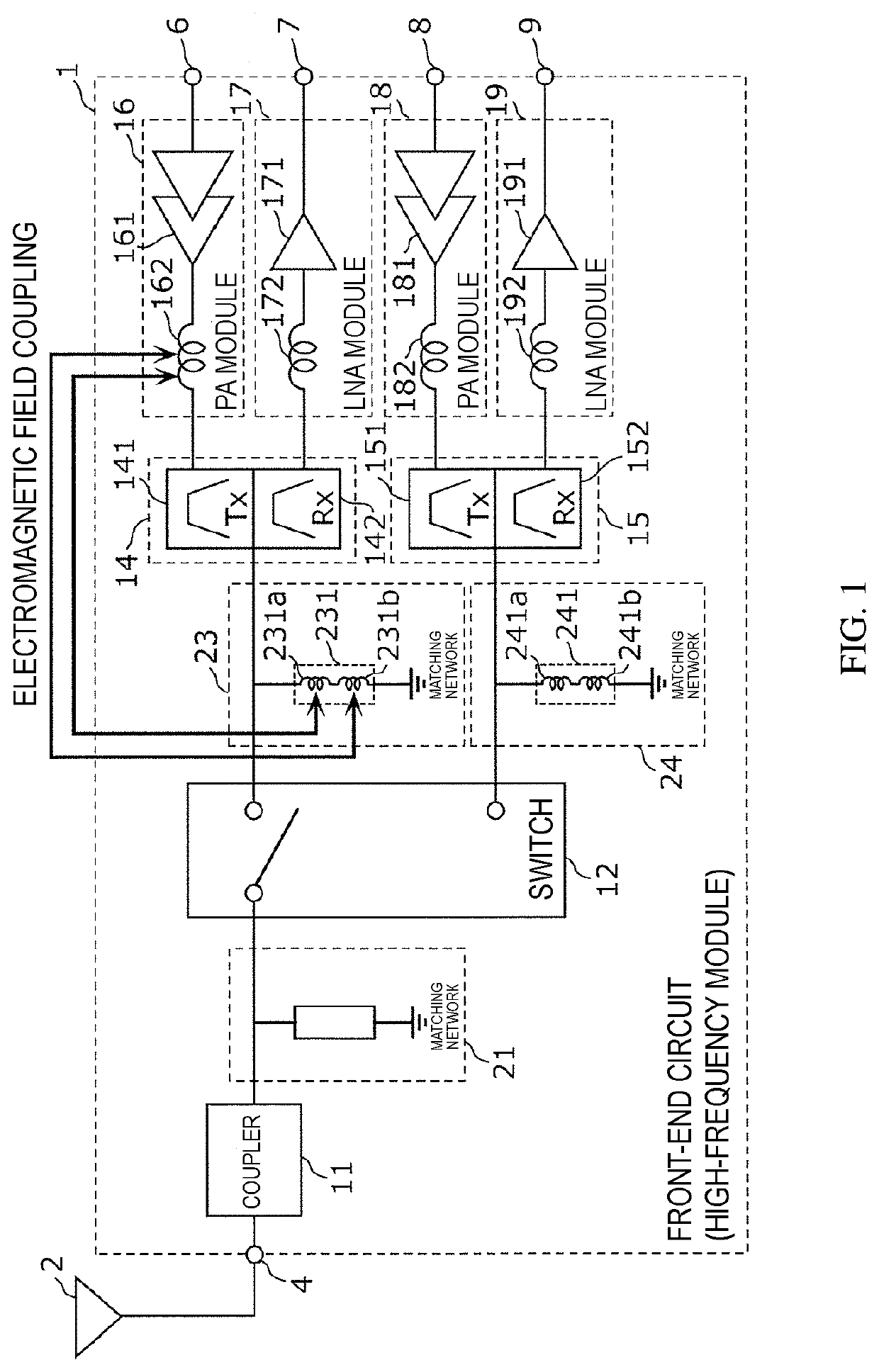
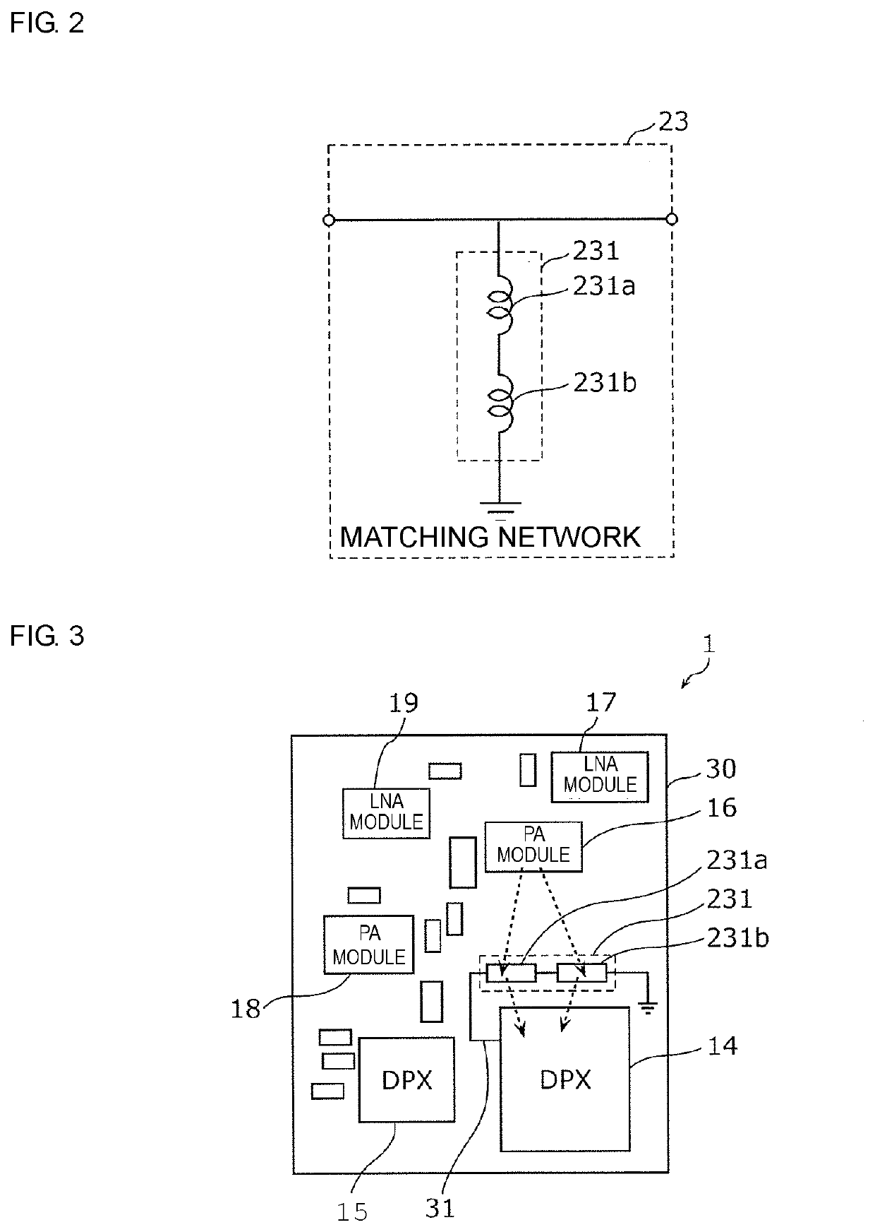
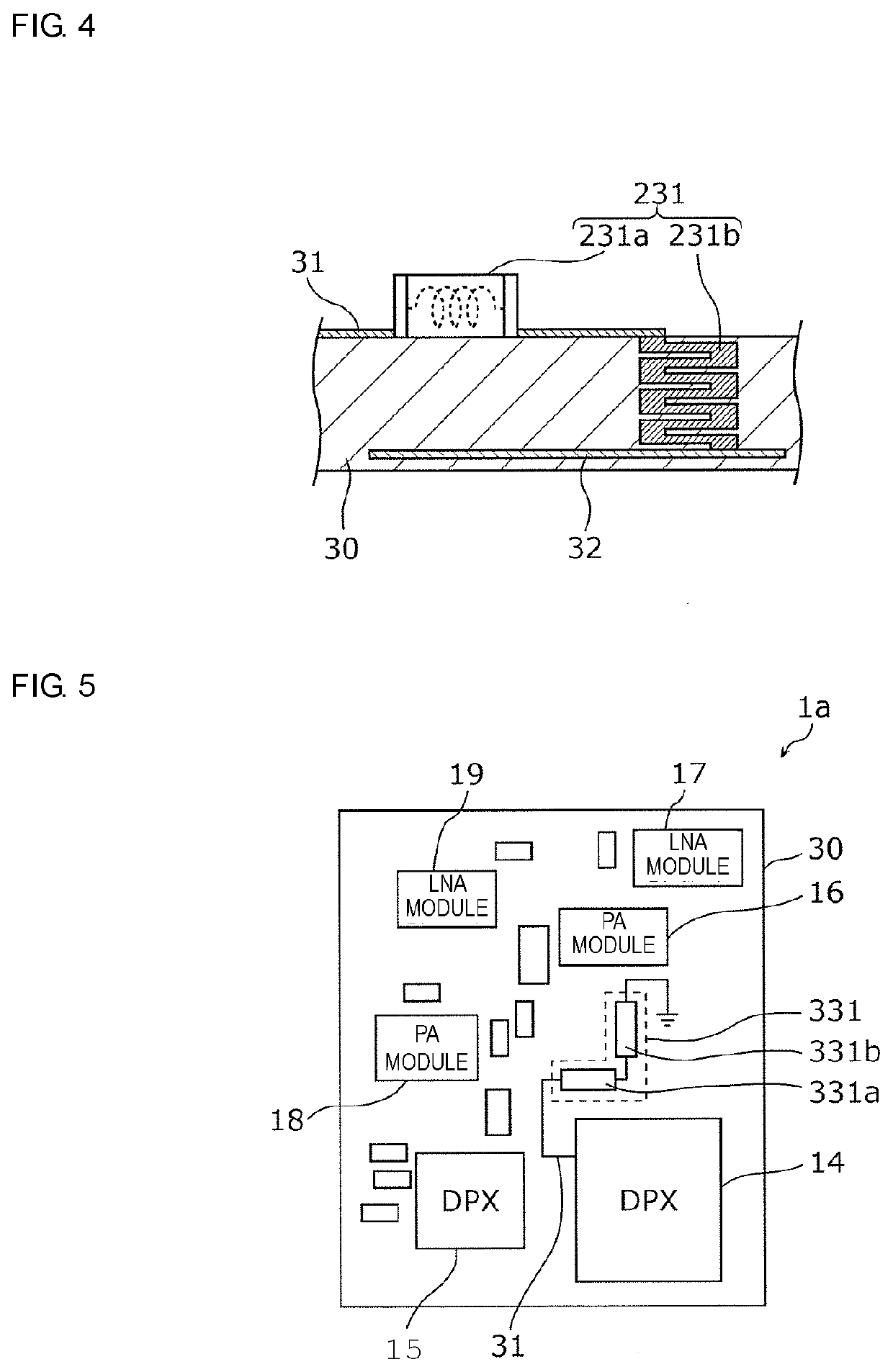
[0035]A first embodiment will be described below with reference to FIGS. 1 to 5. In this embodiment, as a high-frequency module, a front-end circuit used in a communication device will be described as an example.

[0036]First, a configuration of a front-end circuit 1, which is a high-frequency module according to this embodiment, will be described. FIG. 1 is a schematic configuration diagram illustrating an example of a configuration of the front-end circuit 1 according to this embodiment.

1. Configuration of Front-End Circuit

[0037]The front-end circuit 1 is a high-frequency module that performs filtering on an amplified high-frequency signal, switching between a transmission signal to be transmitted to a receiver and a reception signal received from the receiver, and so forth. A high-frequency signal outputted from the front-end circuit 1 is transmitted from an antenna 2 to a base station. In this embodiment, the front-end circuit 1 is used in a communication device that transmits and...

second embodiment

[0106]The front-end circuit 1 described in the first embodiment may be used as the front-end circuit 1 of a communication device as described below. FIG. 6 is a schematic configuration diagram illustrating a configuration of a communication device 100 according to this embodiment.

[0107]As illustrated in FIG. 6, the communication device 100 includes the front-end circuit 1, an RF signal processing circuit (RFIC) 110, and a baseband signal processing circuit (BBIC) 120.

[0108]In the communication device 100, the input-output terminal 4 of the front-end circuit 1 is connected to the antenna 2 as described in the first embodiment. Furthermore, the input-output terminals 6, 7, 8, and 9 of the front-end circuit 1 are connected to the RF signal processing circuit 110 provided at a subsequent stage. The RF signal processing circuit 110 is connected to the baseband signal processing circuit 120 provided at a subsequent stage. Furthermore, the baseband signal processing circuit 120 is connecte...


PUM

PropertyMeasurementUnit
frequencyaaaaaaaaaa
frequencyaaaaaaaaaa
frequencyaaaaaaaaaa

Abstract

A front-end circuit (1), which is a high-frequency module, includes an input-output terminal (4); a duplexer (14) electrically connected to the input-output terminal (4); an LNA (171) electrically connected to the duplexer (14); a PA (161) electrically connected to the duplexer (14); a matching network (23) provided between the input-output terminal (4) and the duplexer (14) and including an inductor (231); and a matching network provided between the duplexer (14) and the PA (161) and including an inductor (162). The matching network including the inductor (162) is an output matching network configured to perform impedance matching between an output terminal of the PA (161) and the duplexer (14), and the inductor (231) includes a plurality of inductors (231a and 231b) connected in series.

Description

[0001]This is a continuation of International Application No. PCT / JP2018 / 020647 filed on May 30, 2018 which claims priority from Japanese Patent Application No. 2017-113338 filed on Jun. 8, 2017. The contents of these applications are incorporated herein by reference in their entireties.BACKGROUND OF THE DISCLOSUREField of the Disclosure[0002]The present disclosure relates to a high-frequency module.Description of the Related Art[0003]In the related art, in a high-frequency module using high-frequency components, such as a duplexer, a power amplifier, and a high-frequency filter, the high-frequency components are produced as separate components and are discretely mounted on a surface of a substrate. In this case, the high-frequency module increases in size, and the cost thereof also increases. Thus, in a recent high-frequency module, some components of these high-frequency components are built into a substrate, and the remaining components are mounted on a surface of the substrate, ...

Claims


Application Information

Patent Timeline
Patent Type & Authority Applications(United States)
IPC IPC(8): H01F27/28H03H7/38H03H7/46H03F3/21H04B1/50
CPCH04B1/50H01F27/2804H03F3/21H03H7/463H03H7/38H01F17/0013H03F3/195H03F3/245H03F3/72H03F2200/294H03F2200/451H03F2203/7209H04B1/18H04B1/525
Inventor NAKAGAWA, DAI
Owner MURATA MFG CO LTD
Learn More