Optical transmission/reception module

a technology of optical transmission and reception module, applied in the field of optical transmission/reception module, can solve the problems of increasing noise in the signal caused by stray light propagating inside the substrate, and achieve the effect of reducing the deterioration of the reception sensitivity

Active Publication Date: 2016-06-16
NEC CORP
View PDF6 Cites 3 Cited by
  • Summary
  • Abstract
  • Description
  • Claims
  • Application Information

AI Technical Summary

Benefits of technology

[0018]The optical transmission / reception module of the present invention can reduce deterioration of the reception sensitivity of the light receiving element.

Problems solved by technology

In particular, the stray light propagating inside the substrate becomes a cause of increasing noise in the signal, as a result of its reentering the optical waveguide or entering the light receiving element connected to the optical waveguide.

Method used


Image

  • Optical transmission/reception module
  • Optical transmission/reception module
  • Optical transmission/reception module

Examples


first exemplary embodiment

[0031]Hereinafter, an exemplary embodiment of the present invention will be described using drawings. However, the exemplary embodiment does not limit the scope of the present invention.

[Description of Configuration]

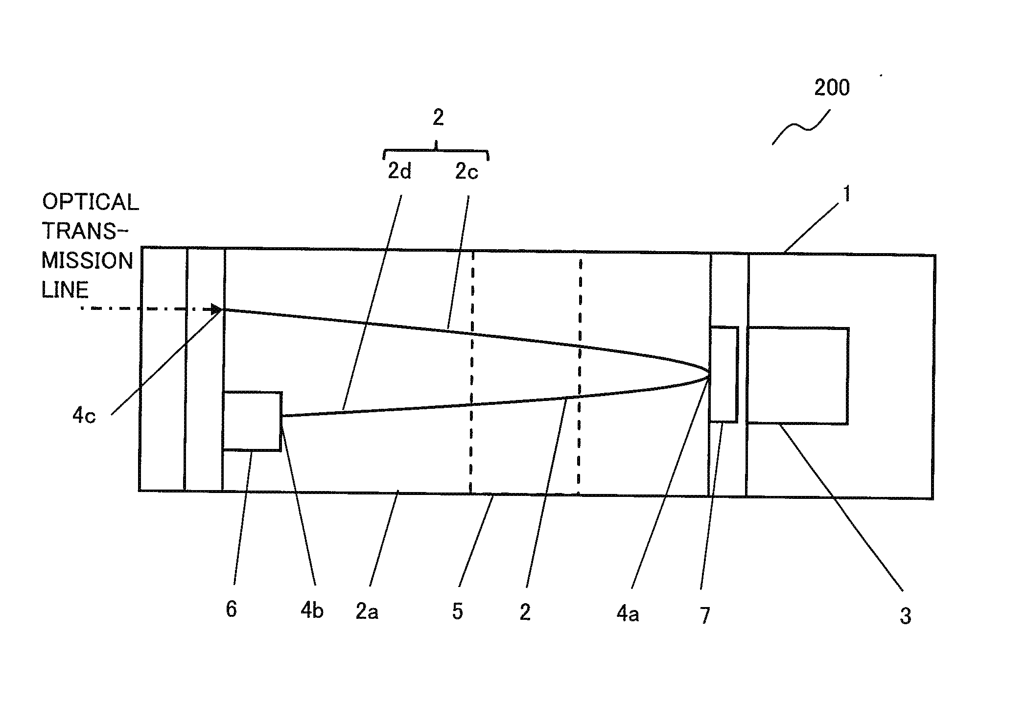
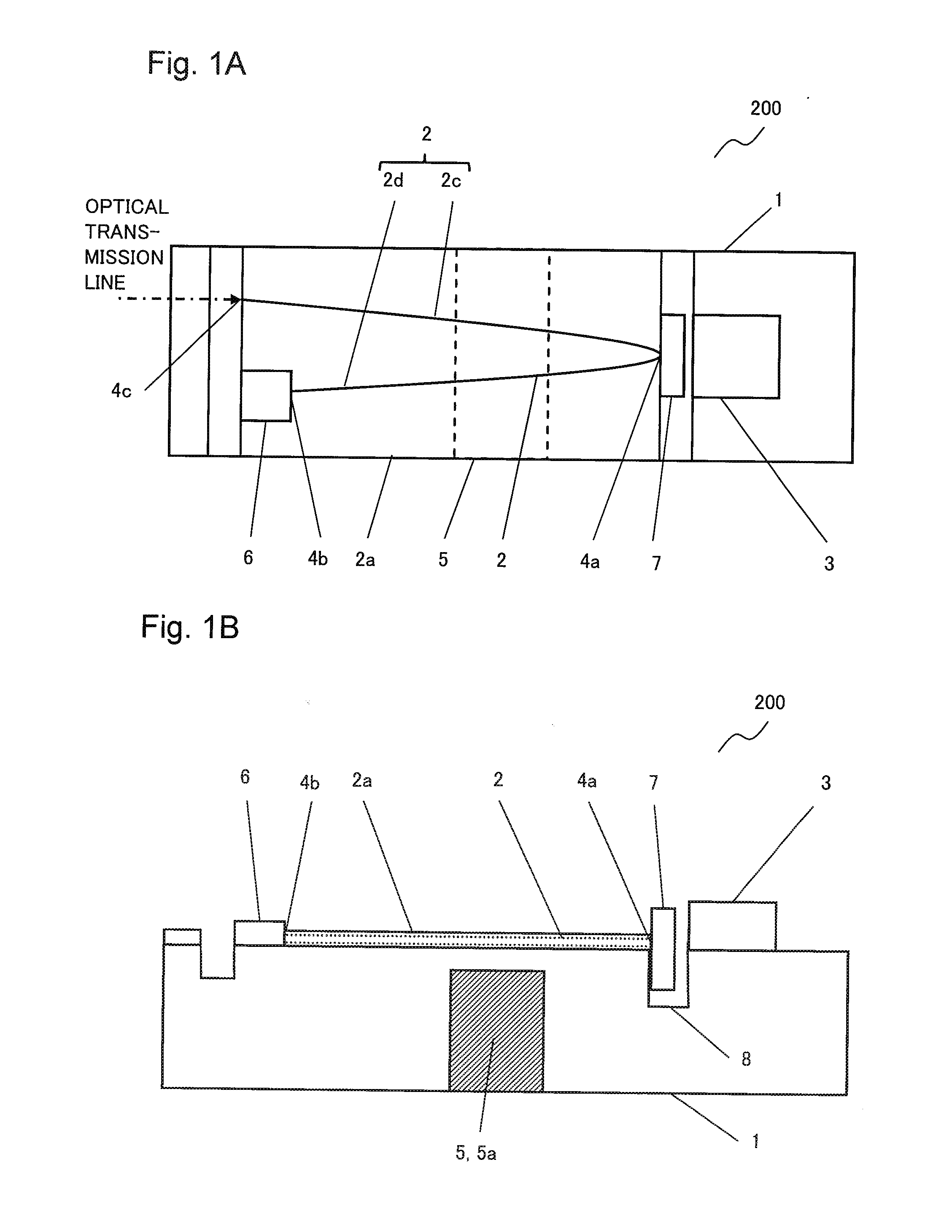
[0032]FIGS. 1A and 1B are a top view and a side view, respectively, of an optical transmission / reception module 200 in the present exemplary embodiment. The optical transmission / reception module 200 of the first exemplary embodiment comprises a substrate 1, an optical waveguide 2, a light receiving element 3, a stray light elimination section 5, a light source 6 and a filter 7.

[0033]As shown in FIG. 1A, the optical waveguide 2 formed on the substrate 1 has a turnaround point 4a, one end 4b and the other end 4c. The light receiving element 3 is arranged on the substrate 1 and is optically connected with the optical waveguide 2 at the turnaround point 4a. The light receiving element 3 receives light having been transmitted through the optical waveguide 2, at the turnaround...

example 1

[Description of Configuration]

[0057]FIGS. 5A and 5B are a top view and a side view, respectively, showing an example of the optical transmission / reception module. As shown in FIGS. 5A and 5B, an SiO2 layer 2a is formed on a Si substrate 1a. Also on the Si substrate 1a, an LD 6a corresponding to the light source, a reception PD 3a and a monitoring PD 3b are mounted. As an optical transmission line outside the module, an optical fiber is mounted. Here, the monitoring PD 3b is a monitoring unit which monitors light emitted from the surface (rear surface) of the LD 6a on the opposite side to one end 4b. As shown in FIGS. 5A and 5B, a recessed section 8 is provided at a turnaround point 4a of an optical waveguide 2 formed in the SiO2 layer 2a on the Si substrate 1a. In the recessed section 8, a WDM filter 7a is installed at the turnaround point 4a such that light having propagated in the optical waveguide 2 from the one end 4b is reflected there and then propagates in the waveguide 2 tow...


PUM


Abstract

An optical transmission/reception module includes a substrate, a light-receiving element provided on said substrate, a light source provided on the substrate, an optical waveguide that is formed on the substrate and has a turnaround point, and a filter positioned between the optical waveguide and the light-receiving element. The optical waveguide is optically connected to the light source at one end and is optically connected to the light-receiving element at the turnaround point. There is a stray-light elimination section in the substrate between the light-receiving element and the aforementioned one end of the optical waveguide.

Description

TECHNICAL FIELD[0001]The present invention relates to an optical transmission / reception module, and in particular, relates to an optical transmission / reception module provided with a configuration for reducing stray light.BACKGROUND ART[0002]A fiber optic communication system in widespread use includes mainly a transmitter, an optical fiber corresponding to a transmission line, and a receiver.[0003]At a point of connection between an optical waveguide type transmitter and an optic fiber, an optical signal transformed from an electrical signal is inputted from an optical waveguide within the transmitter to the optical fiber. The optical signal inputted to the optical fiber is then transmitted by the optical fiber. At a point of connection between an optical waveguide type receiver and the optic fiber, the transmitted optical signal is inputted to an optical waveguide of the receiver. The optical signal inputted to the optical waveguide is then inputted to a light receiving element su...

Claims


Application Information

Patent Timeline
Patent Type & Authority Applications(United States)
IPC IPC(8): G02B6/42G02B6/125
CPCG02B6/4206G02B6/4215G02B6/4214G02B2006/121G02B6/125G02B6/4246G02B6/4286G02B6/42
Inventor OGURO, MAMORU
Owner NEC CORP
Why Eureka
Try Eureka