Ultrasound imaging system, operating method of ultrasound imaging system, and computer-readable recording medium

a technology of ultrasound imaging system and ultrasound image, which is applied in the field of ultrasound imaging system, ultrasound imaging system operating method, computer-readable recording medium, etc., can solve the problem of difficulty for users to determine the sensitivity decrease from viewing the image, and achieve the effect of reducing the reception sensitivity

Active Publication Date: 2020-10-01
OLYMPUS CORP
View PDF0 Cites 0 Cited by
  • Summary
  • Abstract
  • Description
  • Claims
  • Application Information

AI Technical Summary

Benefits of technology

[0007]In some embodiments, provided is an ultrasound imaging system configured to generate data of an ultrasound image based on an echo signal received from each of a plurality of elements included in an ultrasound transducer that transmit and receive ultrasound. The ultrasound imaging system includes: a determining circuit configured to determine, using a signal corresponding to the echo signal obtained by receiving from each of the plurality of elements, concerning the elements, whether a decrease in reception sensitivity occurs; and a control circuit configured to cause, based on a position of an element where the determining circuit determines that the decrease in the reception sensitivity occurs, a display to display at least one of display data indicating an image region where sensitivity decreases in the ultrasound image and information for informing that a sensitivity decreased element in which a decrease in reception sensitivity occurs is present. The determining circuit is configured to acquire sensitivity information of the plurality of elements, extract an element having the sensitivity information smaller than a first threshold as a candidate element serving as a candidate of the sensitivity decreased element, and determine, using a statistical value of sensitivity information of a predetermined number of elements located in a near field region of the candidate element, whether a decrease in reception sensitivity occurs in the candidate element.

Problems solved by technology

It is difficult for a user to determine the sensitivity decrease from viewing the image.

Method used


Image

  • Ultrasound imaging system, operating method of ultrasound imaging system, and computer-readable recording medium
  • Ultrasound imaging system, operating method of ultrasound imaging system, and computer-readable recording medium
  • Ultrasound imaging system, operating method of ultrasound imaging system, and computer-readable recording medium

Examples


first embodiment

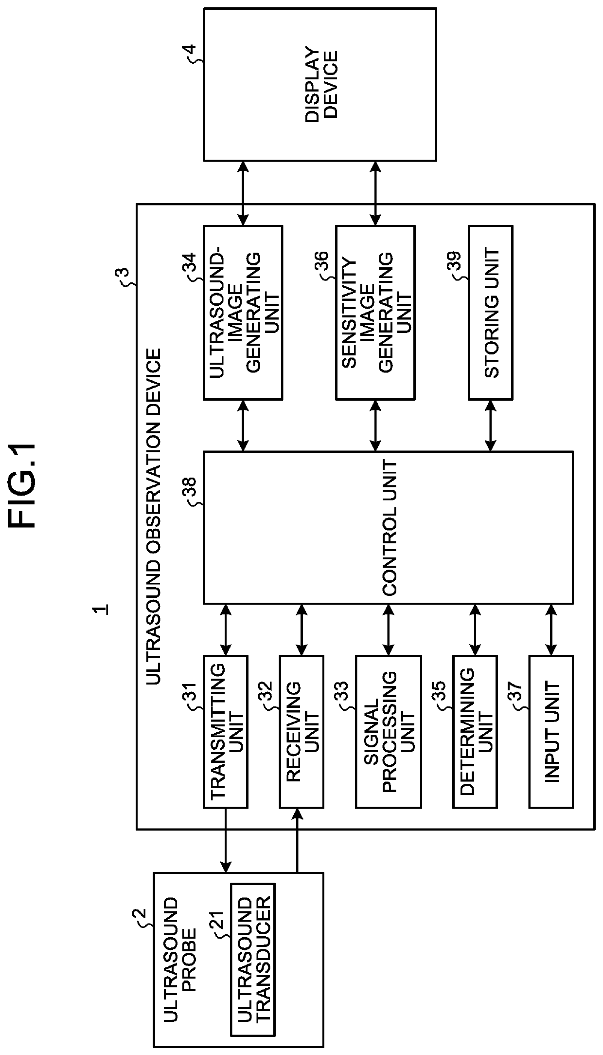
[0025]FIG. 1 is a block diagram illustrating a configuration of an ultrasound diagnosis system including an ultrasound observation device according to a first embodiment of the disclosure. An ultrasound diagnosis system 1 illustrated in the figure includes an ultrasound probe 2 that transmits ultrasound to a subject, which is an observation target, and receives the ultrasound reflected on the subject, an ultrasound observation device 3 that generates an ultrasound image based on an ultrasound signal acquired by the ultrasound probe 2, and a display device 4 that displays the ultrasound image generated by the ultrasound observation device 3.

[0026]The ultrasound probe 2 includes, at the distal end portion thereof, an ultrasound transducer 21 that converts an electric pulse signal received from the ultrasound observation device 3 into an ultrasound pulse (an acoustic pulse) and irradiates the ultrasound pulse on the subject and converts an ultrasound echo reflected on the subject into ...

second embodiment

[0056]An ultrasound observation device according to a second embodiment of the disclosure is different from the ultrasound observation device in the first embodiment in element sensitivity determination processing in a determining unit. A configuration of an ultrasound diagnosis system according to the second embodiment is the same as the configuration in the first embodiment. In the following explanation, components of the ultrasound diagnosis system are denoted by the same reference numerals and signs as those in the first embodiment.

[0057]FIG. 6 is a flowchart illustrating an overview of element sensitivity determination processing performed by the ultrasound observation device according to the second embodiment. Processing in steps S201 to S206 respectively corresponds to the processing in steps S101 to S106 explained in the first embodiment.

[0058]In step S207, the determining unit 35 calculates a sensitivity value of the element i using the RF data received from the receiving u...

first modification

of Second Embodiment

[0072]A near field region may be set according to a reception numerical aperture in generating an ultrasound image. As illustrated in FIG. 8, the reception numerical aperture is sometimes set larger as depth that ultrasound reaches is larger. Accordingly, the number of elements in near field regions may be set larger as the depth is larger. FIG. 9 is a diagram for explaining that near field regions of candidate elements are changed according to the depth. In the first modification, the second threshold used for determination by the determining unit 35 may be set according to the depth.

[0073]FIG. 10 is a diagram illustrating a display example of a sensitivity image in the first modification. A sensitivity image 300 illustrated in the figure displays two sensitivity decreased parts 301 and 302. The sensitivity decreased part 301 and the sensitivity decreased part 302 have different line lengths. This indicates that, in the sensitivity decreased part 302, a deeper r...


PUM


Abstract

Provided is an ultrasound imaging system configured to generate data of an ultrasound image based on an echo signal received by each of a plurality of elements included in an ultrasound transducer, the ultrasound imaging system includes: a determining circuit configured to determine, using a signal corresponding to the echo signal obtained by receiving from each of the plurality of elements, concerning the elements, whether a decrease in reception sensitivity occurs; and a control circuit configured to cause, based on a position of an element where the determining circuit determines that the decrease in the reception sensitivity occurs, a display to display at least one of display data indicating an image region where sensitivity decreases in the ultrasound image and information for informing that a sensitivity decreased element in which a decrease in reception sensitivity occurs is present.

Description

CROSS-REFERENCE TO RELATED APPLICATION[0001]This application is a continuation of PCT International Application No. PCT / JP2018 / 047107 filed on Dec. 20, 2018, which designates the United States, incorporated herein by reference, and which claims the benefit of priority from Japanese Patent Application No. 2017-244257, filed on Dec. 20, 2017, incorporated herein by reference.BACKGROUND1. Technical Field[0002]The present disclosure relates to an ultrasound imaging system, an operating method of the ultrasound imaging system, and a computer-readable recording medium.2. Related Art[0003]In an ultrasound diagnosis system that performs diagnosis using an ultrasound probe, it has been requested to, every time the ultrasound probe is connected to an ultrasound observation device, inform a state of an ultrasound transducer included in the ultrasound probe to a user.[0004]In an ultrasound probe of an electron scanning type, a plurality of elements included in an ultrasound transducer are drive...

Claims


Application Information

Patent Timeline
Patent Type & Authority Applications(United States)
IPC IPC(8): A61B8/08A61B8/14A61B8/00G01S7/56G01S7/53G01S15/89
CPCG01S15/8906A61B8/463A61B8/5269A61B8/469G01S7/56A61B8/145A61B8/5207A61B8/54G01S7/53G01S7/5205G01S15/8915G01S7/52073G01S7/52071A61B8/00
Inventor SABATA, TOMOHIRO
Owner OLYMPUS CORP
Why Eureka
Try Eureka